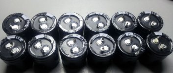
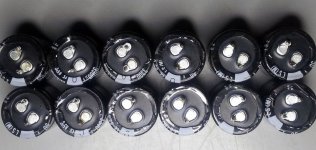
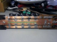
Looks like the caps survived the high heat. The plastic shell warped at a few spots but the paint on the aluminum shell is intact. I'm going to try simply putting them in the correct rotation (with a couple coats of the liquid tape between the caps and the copper) before I disassemble the rest of the build.
Edit: And turning the diodes around to the original orientation.")
Edit: And turning the diodes around to the original orientation.
Attachments
Last edited:
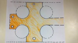
Bob, I had an idea for your 0v bus. This would be a little labor intensive but it might help you localize your heat while soldering. As you can see from the attached "professional" rendering that you could first drill out larges holes to create voids in the sheet and then cut the rest with a bandsaw or scrollsaw etc. You could also drill your through holes closer to the edge which I know you mentioned. This should give your heat only one direction to escape and keep it where you need it just long enough.
The only problem I see with removing material is then the awg equivalent starts to drop, but I guess without some math we really don't know what it is now.
The only problem I see with removing material is then the awg equivalent starts to drop, but I guess without some math we really don't know what it is now.
Attachments
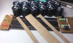
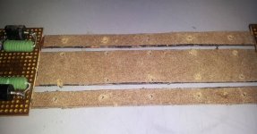
I've been working on a liquid cooler for the discrete amp I'm testing and thought about the leftover 1/32" (.75 mm) automotive paper gasket material I used. Will glue some on the copper for extra insulation.
Fear not - - I will do a build with all the suggested improvements after all these bugs are worked out.
Fear not -
- I will do a build with all the suggested improvements after all these bugs are worked out.Attachments
Bob, I had an idea for your 0v bus. This would be a little labor intensive but it might help you localize your heat while soldering. As you can see from the attached "professional" rendering that you could first drill out larges holes to create voids in the sheet and then cut the rest with a bandsaw or scrollsaw etc. You could also drill your through holes closer to the edge which I know you mentioned. This should give your heat only one direction to escape and keep it where you need it just long enough.
The only problem I see with removing material is then the awg equivalent starts to drop, but I guess without some math we really don't know what it is now.
Thanks, I might try that on the next one. As you were posting I was about to off to the hobby store to replenish my Dremel bits and cutters. For now, I'm going to give what's in the picture a try on this one. I'll keep the remaining copper as least as wide as the outside rails.
In any event, the support of a full length perf or fiberglass board will be added.
Attachments
So the moral of the story is not only "R T F M", but also "Build it as designed".
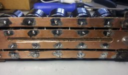
The rebuild produces + 33.1 and -33.0 VDC...
Thanks for hanging in there with me Daniel, and SoIL4X4 for your support.
Been a fun trip !! Now I are a expert.
BTW: A pic of the gasket material applied and the cut-out. Soldering was a breeze this time.
The rebuild produces + 33.1 and -33.0 VDC...
Thanks for hanging in there with me Daniel, and SoIL4X4 for your support.
Been a fun trip !! Now I are a expert.
BTW: A pic of the gasket material applied and the cut-out. Soldering was a breeze this time.
Attachments
Last edited:
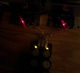
CAN YOU HEAR THAT ????
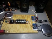
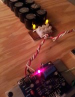
I almost forgot what all the power supply stuff was about. The amps are playing, the bulb tester is out and everything is at room temps. I am again really impressed at the quality of this chip (even on these tiny speakers) and am anxious to get on with the optimized design.
Thanks to all again.
I almost forgot what all the power supply stuff was about.
The amps are playing, the bulb tester is out and everything is at room temps. I am again really impressed at the quality of this chip (even on these tiny speakers) and am anxious to get on with the optimized design.Thanks to all again.
Attachments
Oh, that's good to hear. KUDOS!!!bcmbob said:The power supplies are great - providing very stable and responsive energy for the amps. I plugged in a regular power cord and the amps are really singing.
You just made a successful hi-charge (high dynamics) CRC (low noise) power supply. YAY!! And you did the audiophile features by layout, by design and by component value so that it didn't require audiophile parts. YAY!!!
Heatsink:bcmbob said:I'll hook them up to the big speakers in the morning.
Ah, before that event with the big speakers, you might want to add some u-channels or some free CPU heatsinks onto those heat spreaders. TDA7294's softie limiter (almost transparent except for muddy) is both thermally limited and thermally irritated.
I'm actually somewhat glad you started with small heat spreaders because that lets you find out if the chip is running reasonably (would be piping hot if oscillating), but I guess you found out already, so you might want to boost the heatsink before that event with the big speakers.
Bottleneck:
Basically, there's constipation at the 22u and 47u over on the small signal (left) side of the board that will cause 2nd order harmonic distortion (until those caps are replaced with larger).
The bootstrap and nfb cap (feedback-shunt cap), are a bit too small to show off well with big speakers.
Generally, you could transplant the 47u to the bootstrap, so now the bootstrap is twice as big.
And since 100u caps are really easy to find in decent quality and since the NFB cap (feedback-shunt cap) is near the edge of the board. . lolz, gotta nifty kludge here. . . 100u topside and another trackside, just sticking out the side. Makes 200u. That's slightly undersize, but 4 times larger than the 47u on the schematic at post 1. Even with 200u, it will still have a warm sound.
Clearing up the 2nd order harmonic distortion might make the midrange seem louder. The fix for that is larger amplifier board power caps and possibly a rail to rail cap. These components can be located at the dc power input are of the amplifier board.
So, after you get those areas balanced out, it should sound clearer.
Feedback resistor:
The kit has an insanely circuitous path for the feedback resistor. An inductor (long pcb traces) series with the feedback resistor is bad for higher gain at HF and RF as well as generally imprecise feedback. That resistor needs moved trackside between pins 2 and 14, right on the pins. Have a look at the datasheet's pinout chart. You'll see that putting the feedback resistor right on the chip pins is easy to do.
Last edited:
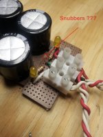
........... We forgot to snub the secondaries for audio quality. Instead of those little green blocks, you can install Kean's 50R trimmer + 2u polyester cap (variable RC to snub the secondaries) at that location. ..............
Hey Daniel,
The power supply is excellent. The dynamics, punch, bass and stage all sound better. I'll add some fins to the heat sink later today.
I couldn't find any information on the "Kean's" item. Will the Bourns trimmer work? Where do I put it and how do I use the variability aspect?
You have presented several versions/designs - some with stacked resistors, cap count from 10 - 16 and different cap values. I used 3300 uF. Do you consider that the best choice? In keeping with the tread theme, which parts combination would you choose as "optimal" for this particular chip/kit? I have delayed my Mouser order to accommodate that info as well as the mods you listed in the last post. I will keep my "learner" PS build and start form scratch on a final.
Also, though some claim no audible difference, would you recommend discrete PS units and/or transformers for the TDA7294? (BTW, the PS dissipates quickly within 1-2 seconds.)
Now that the power supply works, I'll take back half the bad things I said about you!


Attachments
Thanks for the review! And, congrats on the build!The power supply is excellent. The dynamics, punch, bass and stage all sound better.
There's no doubt that a power supply is an audio component.
It is quite likely that you already got it perfect and therefore I can't suggest any large changes. The series element could be made stronger by using several paralleled 3w metal film resistors instead of the single 5w resistor. And, with CRC power supplies, there is some sport in finding the perfect pi filter resistor value. http://www.sengpielaudio.com/calculator-paralresist.htmbcmbob said:You have presented several versions/designs - some with stacked resistors, cap count from 10 - 16 and different cap values. I used 3300 uF. Do you consider that the best choice? In keeping with the tread theme, which parts combination would you choose as "optimal" for this particular chip/kit? I have delayed my Mouser order to accommodate that info as well as the mods you listed in the last post. I will keep my "learner" PS build and start form scratch on a final.
This resistor value affects midrange tone, somewhat like the rail to rail filter, and both work by removing noise. *It might be easier to install the rail to rail filter at the amplifier board before choosing the CRC resistor value, if indeed one is out to find the perfect value.
If using 4 ohm speakers, you can change the 6a standard diodes (0.67v) over to series pairs of fast silicon diodes, such as FR or MUR, (0.45v+0.45v=0.9v) which will adapt the rail kicker action to fit the higher wattage amplifier and still meet AndrewT's "less than 1v" spec.
Installing Kean's secondaries snubbers should make the most important changes of all.
But, if you do want to build another supply differently, I might suggest to use the Nichicon FW 3300u caps. That and some black lacquer on the boards would make a beautiful black and gold show. The Nichicon FW have a better reputation for HF performance; however, you've increased HF performance of ordinary caps by 5x from paralleling them for lower loss, so I cannot tell you that upgrading the model of cap would make any difference. Therefore, I suggest a very real upgrade to 63v caps which can handle a wider variety of project voltages. That combination is here: UFW1J332MRD Nichicon | Mouser
That's right when loaded with a pair of amplifiers that have the speakers connected (condition is loaded power supply And loaded amplifiers makes a fast drain).bcmbob said:(BTW, the PS dissipates quickly within 1-2 seconds.)
However, 1-2 seconds is not quite right if that's the unloaded drain time. Do both sides drain at the same speed?
We have an additional experiment to do, involving:bcmbob said:Also, though some claim no audible difference, would you recommend discrete PS units and/or transformers for the TDA7294?
4 of MBR1045 (or similar MBR shottky diode)
and
either 4 of FB73 or two knots
The MBR diodes go in SERIES to V+ and V-, located at the DC input point at the edge of each amplifier board.
The cable knot or FB73's are located where the power cable goes into those diodes.
This mod cuts the crosstalk blur in half, so it is twice as effective as stereo but half as effective as monobloc/dualmono.
Traditionally, 4 regulators are used to create virtual dual mono, VDM; however, if one wanted unregulated VDM, then I propose it is possible to use schottky.
An alternative (slightly less favorable) location is to create a neat little daughtercard with the 4 FB73 and 4 MBR schottky that can plug into the output edge of the power supply board. It is series element (individualized per each amplifier), and MBR schottky has a miniscule voltage drop. This approach was previously drawn on my power supply schematics. So, if you go with the daughtercard approach, then you've got a dandy little dual mono adapter.
Advantages of VDM-Schottky:
♦ Does not complicate the grounding.
♦ Cost less than additional power supply for dual-mono.
♦ More efficient than regulators for virtural dual mono.
♦ If at the amplifier board, reduces DC cable length versus audio caveats (you can use thick and or short length cables if you want to).
Disadvantages:
♦ Because it didn't complicate the grounding, VDM-Schottky can't provide as much stereo separation boost as real monoblock/dualmono.
♦ Because of using only one transformer, one can't precisely constrain the current available to each amplifier. Compare: With a stereo build, each chip can have access to the full current output of the power supply (might be a "concern" with 4 ohm speakers); however, with real monoblocs, you could precisely choose the current available to each chip. So, with a real monoblock, it is unnecessary to give each chip access to twice as much current as it needs. For example, with the little LM1875 chip, the stereo builds break easily; however, LM1875 monoblocs with 1a transformers are very durable.
Sorry for the huge amount of text--the prospect is actually very simple and could probably be done faster than reading all that.
Keantoken's snubber dial. . .bcmbob said:I couldn't find any information on the "Kean's" item. Will the Bourns trimmer work? Where do I put it and how do I use the variability aspect?
You can install the variable RC's where you had previously installed the little green terminal blocks. That potentiometer works, but you can use a less expensive model if you want to. First you put its center pin onto either one of its outboard pins to create a varaible resistor. Next you put it series to a polyester cap of 1u or 2u or some similar figure. Now you have an RC--a variable RC. This is to snub the transformer secondaries. Variable RC = old fashioned tone control dial. In this case using it on the AC (transformer secondaries) side, muffles the power noise, not the audio.
With your voltage output reading (last time) indicating that one of the transformer secondaries is "louder" than the other, start on that side, with unloaded supply and the voltmeter hooked up. Set the snubber for lowest voltage, so that we're pretty sure it does something. It may vary only a volt, so an analogue meter might make more sensible readings. Next, dial in the other side for same voltage. After you have both equalized and lowered the noise powered voltage on both rails, that's "in the ballpark" and you can reconnect the amplifier and fine tune. This prospect may take some time. The settings are unique per each transformer.
This is like a top-secret audiophile thing where engineers will spend hours with their scopes. . . but Keantoken gave us a convenient and easy little dial to do that job. Awesome.
Last edited:
Oops!
This type: http://www.mouser.com/Passive-Compo...z0x7a1Z1z0x7ld&Keyword=3w+metal+oxide&FS=True
and
This: http://www.sengpielaudio.com/calculator-paralresist.htm
For a value within 0.22R to 0.39R range.
This approach creates a high wattage, non-inductive, resistor at low cost. And, without reliance on advertisements, it is truly non-inductive.
Caveat: You'll need to minimize pin length so it doesn't look like a fish net. It needs one big solid lead, not a bunch of small leads.
P.S.
The 0.24 ohm resistor that you already have, plus some pin length shown in the photos for approximately 0.27R is in the centerpoint of the applicable range. But, it is a 5w resistor and I know that you have a stereo build and some 4 ohm speakers, which is a high power application and probably needs a stronger wattage resistor of same value. Just upgrade the wattage rating.
Should have been "several paralleled 3w Metal Oxide resistors"The series element could be made stronger by using several paralleled 3w metal film resistors instead of the single 5w resistor.
This type: http://www.mouser.com/Passive-Compo...z0x7a1Z1z0x7ld&Keyword=3w+metal+oxide&FS=True
and
This: http://www.sengpielaudio.com/calculator-paralresist.htm
For a value within 0.22R to 0.39R range.
This approach creates a high wattage, non-inductive, resistor at low cost. And, without reliance on advertisements, it is truly non-inductive.
Caveat: You'll need to minimize pin length so it doesn't look like a fish net. It needs one big solid lead, not a bunch of small leads.
P.S.
The 0.24 ohm resistor that you already have, plus some pin length shown in the photos for approximately 0.27R is in the centerpoint of the applicable range. But, it is a 5w resistor and I know that you have a stereo build and some 4 ohm speakers, which is a high power application and probably needs a stronger wattage resistor of same value. Just upgrade the wattage rating.
Last edited:
Since you haven't yet resolved the small signal bottleneck of the amplifier board then the only power supply improvements you could do at this time are:
♦ Definitely try Kean's variable RC's for snubbing the transformer secondaries.
♦ Possibly experiment with the VDM splitter for stereo width enhancement.
But, you need to postpone other tweaks until after the amplifier has been repaired to play full bandwidth, in order to avoid a round robin redo time consumption situation, that is bound to happen if we fixed the wrong spot first. So, with the bottleneck still in place, most tweaks will work like airing a flat tire up with Fix-A-Flat where you end up having to remove it before actually fixing the tire. Instead, we should probably try to fix the right spot first.
Last edited:
VDM experiment
Virtual dual mono, VDM with schottky--cheaper than regulators, similar approach
Purpose = "crosstalk blocker" at less cost than dual mono.
Good part: MBRF1045-E3/45 Vishay Semiconductors | Mouser I like the insulated casing--safer than exposed tab, and MBRF1045 is a highly qualified low loss schottky. Conveniently, he can wear an FB73 ferrite as a bracelet for an easy way to add high quality power filtering.
Low cost part: SL44-E3/57T Vishay Semiconductors | Mouser A sturdy budget 8a schotty
VDM takes 4 low loss Schottky diodes, like this:
V+ Right channel
V- Right channel
V+ Left channel
V- Left channel
If it helps to make sense of it, use regulators instead, for the same stereo separation, crosstalk blocker, feature at higher cost. The schottky are far more efficient but don't provide regulated power.
P.S. Refer to KSTR's post #117 for more information.
Last edited:
Im wondering what could be the specific driver requirements of Tda7294.I think it needs a good speakers. Im also confuse on what "maximum no of speaker outputs" is ?Does it mean like 3,4 speakers can be paralleled or with passive crossover.I need a tweeter ,,can anyone suggest me a good size,watt of it.
I'm wondering what could be the specific driver requirements of Tda7294. I think it needs a good speakers. I'm also confuse on what "maximum no of speaker outputs" is?
One chip is rated to power One woofer of 6 or 8 ohms. For the rest of your question, here's a link to the speakers department of DIYaudio: Multi-Way - diyAudio
- Status
- This old topic is closed. If you want to reopen this topic, contact a moderator using the "Report Post" button.
- Home
- Amplifiers
- Chip Amps
- Optimizing TDA7294 Output