I agree. How fortunate to have someone on the forum who's day job is designing these little amps - specifically the TDA729x series.How perfect is that !! The DIY gods have truly blessed us. I'm getting excited now.")
In the spirit of keeping this little venture simple and inexpensive (at first anyway), why not take the point-2-point that Daniel put forth and instead of a full-blown PCB, mock up the best layout on a perf board? That gives us the best of both worlds to experiment with further layout tweeking (to help eliminate loops) and allow for different component choices.
Klaus - Did I understand you correctly in an earlier post where you recommended the PSU on the same circuit board as the amp. I've often heard that the 'better' option is to remove the PSU from the amp PCB. Am I mistaken?
Bob - I just completed a small amp using the TDA7294. I went with stock amp kits from my favorite China vendor. No exotic parts swapped in. I haven't done a lot of critical listening yet, because the gain on my new Doug Self preamp just blows the volume up on all my amps that don't have volume controls on them! The 7294 also seems to be running a little hot (I guess, @ about 53 degrees C.) I don't know if that's normal or not. I think my heat-sink needs to be beefed up some.
Rick
Attachments
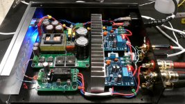
That's the exact same kit I have. I'm still on a slab of plywood. Your build looks terrific and I'm going to look closely for ideas.
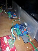
I just have a temporary heat sink of 1/4" x 3" x 4" flat stock but haven't had any heat related problems even after extended hours of operation.
I'm game to try a P2P if someone can provide a BOM. Sounds like fun.
My setup is JRiver to a Mini2496 DAC to the amps. Haven't found the need for a pre, though I did put the JC-2 clone in for an experiment. It didn't help much as the top end of the amp still needs to be cleaned up. More of the same isn't better
Attachments
Last edited:
I would say so, it offers te best compromise. Routing is easy as you can go directly through NC pins. 7295/7296 are the same with derated output power (smaller output transistors).Klaus - with your experience is the 7294 the best of that series for a project like this?
7293 is the mother chip and offers simple paralleling of several chips (two or three work fine), also it has a clipping detector plus it can withstand a bit more of supply voltage (but *not* more output power or dissipation, so you need paralleling to make use of that unless your speakers are 16 Ohms). Layout for paralleling is a bit cumbersome.
ST has duals, too. TDA7292 for example is OK but not brilliant, dual LM's are quite a bit better there.
So basically the TDA7294 would be my prime choice for a small and nice amp. Unless you happen to have very inefficent speakers or ones which severly dip below 4 Ohms a TDA7294 is good for 50W output powers and "loud enough" without problems other than adequate heatsinking. But even when overloaded (thermally or output current) they don't tend to die with moderate supply voltages.
Test setups running the chip "red hot" at 50W continuous with 120degC at the metal tab for extendend periods of time did not produce any immediate fails or any degradation in measurements, after cooling down again. That is, for genuine parts, I haven't met any fakes so far (but a tiny amount that were "dead out of the box" for no reason).
Last edited:

Rick, opinions vary.IKlaus - Did I understand you correctly in an earlier post where you recommended the PSU on the same circuit board as the amp. I've often heard that the 'better' option is to remove the PSU from the amp PCB. Am I mistaken?
I would not like to have the full supply on the board and keep the rectifiers and a first set of capacitors off-board, as well as any associated local components (snubbers etc). But it can be done of course, the MyRef FE is an example where things worked out OK.
Hi Dario,I would stick to SMDs on one side anyway... if some rework will become necessary it will be a pain desolder SMD parts among TH ones... strictly IMHO.
I didn't mean to avoid SMDs, quite the contrary. What I was trying to say that we are free to use both sides for parts of either kind (done wisely as you mention, of course) and we can use non-standard component alignements (odd angles) and we can extend leads of eg resistors to span across some traces, place THT caps laterally along PCB edges etc.
I didn't mean to avoid SMDs, quite the contrary.
Hi Klaus,
never said that... I'm a supporter of SMDs.
Simply I prefer to keep them all on the bottom side of the board, easier to rework, if needed.
I'm really curious to see your board development process, I expect to learn a lot.
How perfect is that !! The DIY gods have truly blessed us. I'm getting excited now.
It's an incredibly-great stroke of perfect luck, alright! Having wished, many times, that I possessed even a tiny fraction of Klaus's technical knowledge and experience, my guess is that as excited and happy as everyone here feels about being so lucky, they actually still have NO IDEA how lucky they REALLY are, to have Klaus involved. (No pressure, Klaus! <grin>)
Perfboard? Really? [Full disclosure: I haven't read most of this thread, yet.]
Cheers,
Tom
In part this the pcb. to build it.That's the exact same kit I have. I'm still on a slab of plywood. Your build looks terrific and I'm going to look closely for ideas.
I just have a temporary heat sink of 1/4" x 3" x 4" flat stock but haven't had any heat related problems even after extended hours of operation.
I'm game to try a P2P if someone can provide a BOM. Sounds like fun.
My setup is JRiver to a Mini2496 DAC to the amps. Haven't found the need for a pre, though I did put the JC-2 clone in for an experiment. It didn't help much as the top end of the amp still needs to be cleaned up. More of the same isn't better
could you post this information in PDF format.
Perfboard would not be my first choice either, but IMO it seems like a better alternative to a P2P kludge (no offense Daniel). A chip-amp based design screams PCB. I'm just not sure we wanted to go down that path just yet. Given Klaus' comments, maybe any of the PCB kits available from eBay and then come up with a recommended BOM of better/replacements parts.I...Perfboard? Really? [Full disclosure: I haven't read most of this thread, yet.]....
Tom
Rick
I agree. How fortunate to have someone on the forum who's day job is designing these little amps - specifically the TDA729x series.
In the spirit of keeping this little venture simple and inexpensive (at first anyway), why not take the point-2-point that Daniel put forth and instead of a full-blown PCB, mock up the best layout on a perf board? That gives us the best of both worlds to experiment with further layout tweeking (to help eliminate loops) and allow for different component choices.
Klaus - Did I understand you correctly in an earlier post where you recommended the PSU on the same circuit board as the amp. I've often heard that the 'better' option is to remove the PSU from the amp PCB. Am I mistaken?
Bob - I just completed a small amp using the TDA7294. I went with stock amp kits from my favorite China vendor. No exotic parts swapped in. I haven't done a lot of critical listening yet, because the gain on my new Doug Self preamp just blows the volume up on all my amps that don't have volume controls on them! The 7294 also seems to be running a little hot (I guess, @ about 53 degrees C.) I don't know if that's normal or not. I think my heat-sink needs to be beefed up some.
Rick
partner (brother) have the power poara costruirlo PCB that performs well is that amplifier.

The 7294 also seems to be running a little hot (I guess, @ about 53 degrees C.) I don't know if that's normal or not.
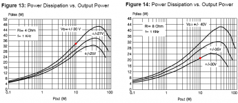
That's normal. The heatsink is very thin and of poor aluminum quality. I would go for no more than 20V supply (lower Pmax) with that heatsink.
I just have a temporary heat sink of 1/4" x 3" x 4" flat stock but haven't had any heat related problems even after extended hours of operation.
It depends on speaker load and power supply rail voltage.
If I wont listen in high power (and have efficient speaker) I will prefer lower voltage to allow smaller heatsink and compact amplifier.
Attachments
In part this the pcb. to build it.
could you post this information in PDF format.
Hey Sergio, Not quite sure what you are asking for. There is nothing on a new design to publish yet. Or is your question about what I'm using to push the kit I have?
In my opinion, surpassing the performance of a P2P kludge, can be done with a professional layout of a double-sided PCB with very few vias, in order to more thoroughly defeat the mad pinout of these chips. I do not have the skills to create advanced PCB, but I would like to buy some.redjr said:. . . a better alternative to a P2P kludge (no offense Daniel).
See the sections:Klaus - Did I understand you correctly in an earlier post where you recommended the PSU on the same circuit board as the amp. I've often heard that the 'better' option is to remove the PSU from the amp PCB. Am I mistaken?
1. Smoothing+Rectifier (the rectifiers and first caps for DC)
Next a cable or resistor or diode or regulator
2. Power supply reservoir "tank" (supports large signal bass)
Next a cable or resistor or diode or regulator
3. Amplifier board power caps (support small signal clarity)
Advanced power circuit:
When there is a regulator or diode followed by small capacitance for providing preamp/predrive with only fast transient support for small signal. . . it is then possible to have significantly large capacitance located on the amplifier board for supporting the output devices large signal, without degrading the small signal.
Non-independent mono-blocks? Okay. Will this do? With only one transformer, it doesn't cost much.Further, I'm not a fan of fully independent mono-blocks (even when in the same chassis), so a complete stereo PCB with most of the supply components on board seems more adequate for most builders I would think. For DIY we also have the option to make use of unorthodox layout/component placement as we do not need to care about feasibility for mass production (which means sticking to all SMT parts located on the same side).
Attachments
Last edited:
^ Yes, something similar to this. The xformer, rectifiers and main big reservoir can be shared while the sections after series resistors or other series elements (and in GND nets also) would be seperated between PCBs, being located on-board. Then a local GND bus connecting PCBs would establish a quiet and common GND. All this applies in case of mono PCBs (or multichannel >2CH), with stereo PCBs things would be rather simple; PSU (P2P or PCB), 3 wires, Amp-PCB.
doubt
I need:
PCB (copper side), can not find it.
Componentized (PCB components). If this
Diagram. If this
an example of PCB:
Hey Sergio, Not quite sure what you are asking for. There is nothing on a new design to publish yet. Or is your question about what I'm using to push the kit I have?
I need:
PCB (copper side), can not find it.
Componentized (PCB components). If this
Diagram. If this
an example of PCB:
An externally hosted image should be here but it was not working when we last tested it.
Perfboard would not be my first choice either, but IMO it seems like a better alternative to a P2P kludge (no offense Daniel). A chip-amp based design screams PCB. I'm just not sure we wanted to go down that path just yet. Given Klaus' comments, maybe any of the PCB kits available from eBay and then come up with a recommended BOM of better/replacements parts.
Rick
Sorry. Now I am re-thinking it...
I guess there are a few general options, with trade-offs, to be considered.
Not needing an etched PCB would probably mean that a lot more people would build one. It would at least mean that it could be more-readily built, and someone who wanted to build one could start almost immediately.
If the sound quality could also be superb, and the result was mechanically good and easy to construct, then not using a PCB pattern would definitely be an option worth considering.
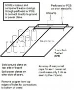
For the reservoir caps, I would like to have consideration given to something similar to Terry Given's cap bank board. It uses a non-etched two-sided PCB. All you need is a drill. Use a slightly larger drill to remove copper from edges of holes for connections to bottom side. Cut cap leads, bend parallel to copper, and solder. Unless two PCBs were used, it would have to have all ground plane on one side and the power plane side would be split into two planes, for the power rails. The chipamp could be located over the line between the power planes. Check out the link and see what impedance Terry measured with his network analyzer!
If a small piece of perfboard or PCB were used for only the chipamp circuit, that board could be mounted on short standoffs, OVER one end of the cap-array PCB. Then, the chipamp's power leads could go down through the small board and connect directly to the power planes. Any ground connections could also go straight down to connect to the ground plane. See attached sketch.
That configuration would also provide more freedom for the layout of the small board.
A set of links to the posts about the wonderful cap-array board is at the bottom of the post at:
(NOTE that Terry meant to say RADIAL, not axial, in the post at the first link!)
http://www.diyaudio.com/forums/chip-amps/224914-lm3886-component-selection-3.html#post3282640
Cheers,
Tom
Attachments
Last edited:
Tom, that looks really nice for powering amplifiers with regulated front end, like this from Ilimzn:

This is great!
The regulators have served as the necessary series element so that we can put big caps to help the output devices do good bass, without making the predrive section unintelligible. I like this schematic for demonstrating have your cake and eat it too. It is compatible with Tom's power board description at post 119.
Last edited:
- Status
- This old topic is closed. If you want to reopen this topic, contact a moderator using the "Report Post" button.
- Home
- Amplifiers
- Chip Amps
- Optimizing TDA7294 Output