I'm curious about the TDA7293, with the inputs shorted (per the datasheet's "modular" schematic), and used merely as output devices for current pump amplifier. It looks almost silly except much easier to heatsink than discrete SMD powerfets, costs less than rare latfets, and the chip amp also has stable production so that the design doesn't have to be changed every few months to accommodate parts availability.TDAs did well in some standard "current pumps" and mixed output impedance amplifiers I designed. Howland type is critical because common mode voltage is high (67% of the output voltage in the MyRefs) and could exceed chip limits, which are unknown for the TDAs other than that the input stage cuts off when pulled to V-. True usable input CM range is something I want to find out in detail sometime, in comparison to the LMs. Both have not specified this parameter in their datasheets so we can only assume a guaranteed range of no more than about 1/10th of the ouput voltage plus some unknown headroom, depending on supply voltages and their balance.
But, that might be a topic for a different thread.
Last edited:
First of all, heat indicates an unhappy chip amp doing too much non-audio work, such as oscillation and/or simply affronted by power supply issues causing a lot of extra work when it tries to amplify that in addition to the audio.I think that might have been what happened, unless it was possibly heat related. But with no signal, I would suspect that the amp would not continue to heat up.
Well, just consider that if it amplifies "only audio" then it should be running very cool.

Fortunately, while you're exploring options, this chip usually responds "the cooler the clearer" which is convenient and straightforward in getting both higher resolution audio and a cooler running amplifier, simultaneously.
P.S.
One way, and perhaps the easiest way, to compensate a chip amp is to increase the power amp gain a bit, and I wouldn't have suggested that except that the Zune MP3 player can perform better and more suitable to amplify when not straining to push a power amp. If you didn't want to change the gain, it is also possible to run a bit less feedback current by raising both the feedback resistor and feedback-shunt resistor to higher values proportionately. So, there's two different adjustments which can be explored. One is for voltage and the other is for current. This can be done separately or together, depending on need and results.
Last edited:
Daniel - Where and how do you add a manual gain control to these little chipamps. Most of the ones I've built have not included any kind of gain control. I don't think it's as simple as adding a pot to the input either, but I have done that with one amp. Am I wrong? I would love to know the correct way to add a proper gain control and when they need to be used. I was using my Zune directly so that I could 'force' some level control on the amp.First of all, heat indicates an unhappy chip amp doing too much non-audio work, such as oscillation and/or simply affronted by power supply issues causing a lot of extra work when it tries to amplify that in addition to the audio.
Well, just consider that if it amplifies "only audio" then it should be running very cool.
Fortunately, while you're exploring options, this chip usually responds "the cooler the clearer" which is convenient and straightforward in getting both higher resolution audio and a cooler running amplifier, simultaneously.
P.S.
One way, and perhaps the easiest way, to compensate a chip amp is to increase the power amp gain a bit, and I wouldn't have suggested that except that the Zune MP3 player can perform better and more suitable to amplify when not straining to push a power amp. If you didn't want to change the gain, it is also possible to run a bit less feedback current by raising both the feedback resistor and feedback-shunt resistor to higher values proportionately. So, there's two different adjustments which can be explored. One is for voltage and the other is for current. This can be done separately or together, depending on need and results.
My spanky new Doug Self preamp has plenty of gain. So much so, that I barely have to turn it up past 8:00 on the dial before it's blowing the walls down. There's literally no way to listen at lower volume levels without having some 'gain' control on my amps to compensate for the massive gain of my pre. Hence my dilemma with using the pre with (at least) the 7294.
I know we're going off topic a bit here... but if I intend to use the new pre with a certain power amp I build, then I need some way to limit the input voltage (gain/sensitivity) of the power amp. I would prefer for it to be variable, but a set, constant resistance would work to. Best approach?
Rick
Optmizing the TDA7294
There are two mods that could be done to the TDA7294 to 'improve' it's performance and increase it's load handling capacity. Both have been covered long ago and only a good pcb needs to be made. Sure lots of members may have already done this as the topic is quite old !
Note that Ilimzn's wonderful explanation of the operation of the 7294 isn't new. He posted the information first in 2006 ! Not many seem to have read it/used it since then !
The concept of adding power driver transistors to the output has been bandied around for a very long time , to increase power handling of several chip amps.
So we just need to supply clean power to the input stage and add a pair of power transistors at the output to bump up the load capability to handle 4 ohms easily at high supply voltages.
I did work on a design but never got round to trying it and the attempt faded away with lots of distractions that arose in the meantime.
Maybe 2013 will bring back the urge to try it again ,especially as I bought several 7294 chips in 2006 !
You need a non-dulling volume-range control?Daniel - Where and how do you add a manual gain control to these little chipamps. Most of the ones I've built have not included any kind of gain control. I don't think it's as simple as adding a pot to the input either, but I have done that with one amp. Am I wrong? I would love to know the correct way to add a proper gain control and when they need to be used. I was using my Zune directly so that I could 'force' some level control on the amp.
My spanky new Doug Self preamp has plenty of gain. So much so, that I barely have to turn it up past 8:00 on the dial before it's blowing the walls down. There's literally no way to listen at lower volume levels without having some 'gain' control on my amps to compensate for the massive gain of my pre. Hence my dilemma with using the pre with (at least) the 7294.
I know we're going off topic a bit here... but if I intend to use the new pre with a certain power amp I build, then I need some way to limit the input voltage (gain/sensitivity) of the power amp. I would prefer for it to be variable, but a set, constant resistance would work to. Best approach?
Rick
Let's fake that feature from Lightspeed Attenuator, but at lower cost. . . Just get a 50K dual-gang (stereo) pot and experiment with adding resistors to both of the outboard pins so that it cannot either go up all the way nor down all the way. You can further experiment by adding a resistor load to the input side. Also get a sack of short length alligator clip leads and clips by themselves to help speed exploration. And then solder the results of your exploration using a miniscule bit of gel flux for assured connection quality. After some play, the volume-range control prospect makes a novel non-dulling potentiometer for about $4, which cost less than the lightspeed attenuator, with the same benefit of not dulling the audio and with the same caveat of limited range. This goes almost all the way up, almost all the way down.
Location: Potentiometers are bad at driving cables, so this sort of device must go in close proximity to the input of a power amp. You can make it as an accessory in a cute little box with input RCA jacks and up to 1 foot "pigtail" RCA cable for output. Or you can actually use it as a power amplifier's volume-range control to get the cable length shorter for somewhat better results.
Loud is loud; but, loud and good is a different matter.
It may be useful to straighten out the source device before amplifying. Discrete buffer is a fun and simple alternative to multi-op-amp projects. These measure at extremely low distortion for measuring equipment; but, to the ear, a good discrete buffer can be amazing. Location of a buffer is as close as possible to the source for which it is useful. A beneficial buffer may be hard to find since descriptions are probably not given in audiophile terms. Since we know that impedance adjustments can make buffers unnecessary, when you find an engineer who consistently uses his buffer design, he's caught red-handed with an excellent block-rocker device that you will very much enjoy. In my opinion, these buffers are a great way to improve the quality of the source that you already own, and more practical or at least considerably faster than a long search for the elusive perfect source, which will, of course have this sort of buffer built in. You can DIY that piece.
Since potentiometers are particularly bad at driving cables, I suggest to put the new volume-range control directly onto the Input of a nice buffer project. I also suggest individual "cancel" switches for both features, because those can be fun and informative to use; and, because any good hi-fi effect always has a cancel switch, no matter if you intend to use the switch or not. Personally, I would mark one switch "boost" and the other switch "turbo" just for fun.
Or like this:
And do consider the buffer, because we need the signal good before the power amp makes it loud.
Last edited:
This would be nice of course, but would surely file under "scope creep". My idea was more like trying to make an excellent but still simple standalone TDA7294 amp.So we just need to supply clean power to the input stage and add a pair of power transistors at the output to bump up the load capability to handle 4 ohms easily at high supply voltages.
To get to a better (at least in terms of any measurments) and more powerful amp which is still quite simple and safe, I'm more inclinded to use 2..3 pcs. 7293s in master/slave config based on the simple amp's powering appoach, then adding a small-signal opamp to form a composite/nested amplifier. Even with the best conditions any standalone 7293/7294 amp will have a quality limit which is best overcome with a composite type of amplifer with high open-loop gain and careful compensation.
Thanks Daniel for your detailed reply. I have used the 50k pot solution on the input of one my recent builds (LJM class D amp). I kept the cables very short (< 2") from the amp inputs. This worked very nicely and it sounds very good. It addresses the issue with my 'over-bearing' pre. I may explore mods that I could easily make to my new Doug Self pre without necessarily affecting its fine specs. It sounds great and is essentially noise free. At some point it will find a permanent home in my preferred stereo rig, but that hasn't happened yet.You need a non-dulling volume-range control?
Let's fake that feature from Lightspeed Attenuator, but at lower cost. . . Just get a 50K dual-gang (stereo) pot and experiment with adding resistors to both of the outboard pins so that it cannot either go up all the way nor down all the way. You can further experiment by adding a resistor load to the input side. Also get a sack of short length alligator clip leads and clips by themselves to help speed exploration. And then solder the results of your exploration using a miniscule bit of gel flux for assured connection quality. After some play, the volume-range control prospect makes a novel non-dulling potentiometer for about $4, which cost less than the lightspeed attenuator, with the same benefit of not dulling the audio and with the same caveat of limited range. This goes almost all the way up, almost all the way down.
Location: Potentiometers are bad at driving cables, so this sort of device must go in close proximity to the input of a power amp. You can make it as an accessory in a cute little box with input RCA jacks and up to 1 foot "pigtail" RCA cable for output. Or you can actually use it as a power amplifier's volume-range control to get the cable length shorter for somewhat better results.
Loud is loud; but, loud and good is a different matter.
It may be useful to straighten out the source device before amplifying. Discrete buffer is a fun and simple alternative to multi-op-amp projects. These measure at extremely low distortion for measuring equipment; but, to the ear, a good discrete buffer can be amazing. Location of a buffer is as close as possible to the source for which it is useful. A beneficial buffer may be hard to find since descriptions are probably not given in audiophile terms. Since we know that impedance adjustments can make buffers unnecessary, when you find an engineer who consistently uses his buffer design, he's caught red-handed with an excellent block-rocker device that you will very much enjoy. In my opinion, these buffers are a great way to improve the quality of the source that you already own, and more practical or at least considerably faster than a long search for the elusive perfect source, which will, of course have this sort of buffer built in. You can DIY that piece.
Since potentiometers are particularly bad at driving cables, I suggest to put the new volume-range control directly onto the Input of a nice buffer project. I also suggest individual "cancel" switches for both features, because those can be fun and informative to use; and, because any good hi-fi effect always has a cancel switch, no matter if you intend to use the switch or not. Personally, I would mark one switch "boost" and the other switch "turbo" just for fun.
Or like this:
And do consider the buffer, because we need the signal good before the power amp makes it loud.
I do like the idea of the Lightspeed Attenuator and in the future may build a portable one with RCA in and out. But it sounds like it 'okay' (maybe not ideal) to use a 50k pot in a power amp as long as it's close to the input.
I'm somewhat of a newbie with building amps and have therefore limited my selection to full kits, or assembled modules so far. I haven't ventured into buffers and some of the other external circuitry that may be required between amps and pre's. Could you point to any threads, or links that provide details on building and using a buffer circuitry? I need to study up on buffers!
Rick
Me too. Analog Line Level looks like an obvious place to find them, but that is not the case. Locations of the most promising buffers are generally in the Solid State and Tube amplifier forums. Probably, that's because a "safe bet" for performance is to put a buffer at the input of the power amp rather than make assumptions about what all sources should do? So, the actual place to research buffers is here: diyAudio - Search Forumsredjr said:Could you point to any threads, or links that provide details on building and using a buffer circuitry? I need to study up on buffers!
Either way, it looks like the purpose is for keeping the large signal impact off the gain stage.This would be nice of course, but would surely file under "scope creep". My idea was more like trying to make an excellent but still simple standalone TDA7294 amp.
To get to a better (at least in terms of any measurments) and more powerful amp which is still quite simple and safe, I'm more inclinded to use 2..3 pcs. 7293s in master/slave config based on the simple amp's powering appoach, then adding a small-signal opamp to form a composite/nested amplifier. Even with the best conditions any standalone 7293/7294 amp will have a quality limit which is best overcome with a composite type of amplifier with high open-loop gain and careful compensation.
If I understand correctly, your plan with the schematic reading inverting mode plus lead lag comp, involves cutting the gain down until compensation is required thereby giving the creative freedom to add much nicer quality compensation--much better than is inside the chip. And a lot less power amp gain is likewise a lot less power supply influence on audio. Then, the majority of the gain task can be relocated to a preamp run on clean power which is a more suitable spot to have the gain. Right?
That plan looks builder friendly.
Generally speaking, I like this prospect of taking one big task and turning it into a few simpler, smaller and more doable tasks (divide and conquer), for the purpose of assuring high quality results.
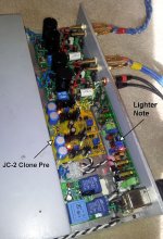
Though I don't want to sound like a sales agent for Stanton, I have had excellent results with this pre. In short, to me it has almost all of the clarity of my Lighter Note (Uriah Dailey - buildanamp.com) but with a healthy amount of gain. I even combined the LN to drive that pre in one build with happy results. I mention both here simply as a couple options to keep in the back of our minds. There are of course many other solutions I haven't built or heard.
Attachments
Daniel,
your guess on my rationale to try inverting is right; drop down the gain to the lowest level, could be as low as only 3x with a powerful pre than can deliver 8Vrms or so.
Inverting has the advantage of an easier scaling of the gain to just the needed level. This can be had with non-inverting, too, but one needs more parts and the source impedance becomes critical.
I plan to try, in the breadboarding stage of things, both inverting and non-inverting with the exact same amp chip, setup and power config etc and compare/check perfomance difference pretty much in realtime, something that didn't happen before and could be worthwhile. Just in case the net benefit of low gain inverting + pre won't be significant, I might go back to standard gain non-inverting, we'll see...
Same thing for seperate power for chip frontend positive rail...
One thing seems clear, though, I'l be using a lot of local supply capacitance, more than ususal, fed from a softer than usual main supply.
Argh, breadboarding setback today.
The multiple paralleled "capacitor strips" that I planned to use didn't work out as good as expected, loop area and hence inductance is still too high, 1.5mm PCB thickness together with non-optimum geometry (long and narrow strips) took its toll... so they're worse than a good compact PCB with them array'ed up in 2D instead of just lining them up in two rows....
The multiple paralleled "capacitor strips" that I planned to use didn't work out as good as expected, loop area and hence inductance is still too high, 1.5mm PCB thickness together with non-optimum geometry (long and narrow strips) took its toll... so they're worse than a good compact PCB with them array'ed up in 2D instead of just lining them up in two rows....
Did you use more than 7 caps parallel?
Although two caps may internally reverberate at the same time as one cap, manufacturing variances (in 10% or 20% tolerance capacitors) begin to foil paralleling ideas whereby the more you parallel, the more slightly different noises there are to add up to the worst capacitor ever made by the hand of man. I've seen the practical limit for no-ballast paralleling recur at about 7 caps parallel in many examples. I hope that helps.
Although two caps may internally reverberate at the same time as one cap, manufacturing variances (in 10% or 20% tolerance capacitors) begin to foil paralleling ideas whereby the more you parallel, the more slightly different noises there are to add up to the worst capacitor ever made by the hand of man. I've seen the practical limit for no-ballast paralleling recur at about 7 caps parallel in many examples. I hope that helps.
Last edited:
This is a geometrical issue, the build has to much intrinsic inductance so that the reduction by paralleling 30pcs. 47u/50V did NOT result in 30 times lower ESL the way I've set them up (but ESR did decrease as expected).
Of course there is something to your point of NOT to parallel too many identical caps to avoid concentrating any ill-effects like a mechanical resonance or any spooky ESR characterstics and such things that one might encounter for any specific make/model of cap...
Of course there is something to your point of NOT to parallel too many identical caps to avoid concentrating any ill-effects like a mechanical resonance or any spooky ESR characterstics and such things that one might encounter for any specific make/model of cap...
This is a geometrical issue, the build has to much intrinsic inductance so that the reduction by paralleling 30pcs. 47u/50V did NOT result in 30 times lower ESL the way I've set them up (but ESR did decrease as expected).
Of course there is something to your point of NOT to parallel too many identical caps to avoid concentrating any ill-effects like a mechanical resonance or any spooky ESR characterstics and such things that one might encounter for any specific make/model of cap...
I don't know about concentrating any identical ill effects. But the more caps in parallel the more it should dilute any defect or ill effect that is not identical in all caps, and the less dependent the array will be on any one cap's properties.
In Terry Given's explanation (in this forum) of the array's geometry optimization, he specifically mentioned not making the arrays long and narrow, because the current needs to spread across the plane to be shared by all of the caps, as well as possible, in much the same (mathematical) way that heat spreads. His suggestion was to use a shape approximating a square, with the input at the middle of one side and the output at the middle of the opposite side. He did also mention offsetting the rows, but mainly for better cooling (by making any air go around all of the caps, instead of just rushing through corridors between rows of them).
Hi Klaus, -
Not exactly sure what type of array you're trying to proto for the 7294, but I was wondering if something like this is what you're after? Maybe not as large of an array. I have not used this particular board, but have thought about getting one just to have around for a future project.
Not exactly sure what type of array you're trying to proto for the 7294, but I was wondering if something like this is what you're after? Maybe not as large of an array.
I have not used this particular board, but have thought about getting one just to have around for a future project.Attachments
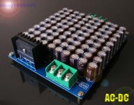
That board sure is nice for the price but using an obsoleted capacitor type (Nippon Chemicon KMY), also it's not low impedance as does not use solid copper planes.
However, as a first filter/reservoir bank it might do well (with enough series resistance with the diode bridge).
However, as a first filter/reservoir bank it might do well (with enough series resistance with the diode bridge).
In using surface mount caps, one can make a vertical daughtercard with the caps on both sides. It reduces the board size dramatically. I still wouldn't put any caps at the "corners" of a square shape board. The 4 (or 8 if double sided) caps at corners would be the "most different" so I would omit them. I'm not sure how a vertically mounted double-sided approach affects your board layout, but assuming it has vias anyway, might as well mount caps to both sides of them. The surface mount computer caps are designed to tolerate "sideways" (any "mini-tower" computer), are available in tighter tolerances and generally have low ESR spec.
P.S.
I'm don't know how this applies to audio but it might work well for radio power supply. EDIT: The thought behind that was that radio worthy power supply can make a really high gain amp run nice and cool; however, you're doing low gain amp with added compensation, and it will probably ignore RF, which is a really much easier approach. When I was reading through all this, it seems that "Plan A" and "Plan B" got mashed together resulting in added complexity that is not required in all cases. Maybe it would be nice to separate the two approaches so that they can be compared.
Last edited:
It works, much better than the long PCB strip. Isolation is only about 200µm thickness (two layers of paper backed adhesive tape), reducing loop area to the practical minimum. Analyser says than this 40 x 40mm copper foil square has a neglegible contributing inductance and resistance, that's what I need to tailor the supply with a solid baseline, without doing PCBs first....I'll try 200µm copper foil today with very thin insulation between them, in about 40mm x 40mm square shapes. These should fare much better at RF than the 20mmx80mm strips of 35µm with 1.5mm spacing.
Last edited:
- Status
- This old topic is closed. If you want to reopen this topic, contact a moderator using the "Report Post" button.
- Home
- Amplifiers
- Chip Amps
- Optimizing TDA7294 Output