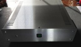
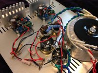
Finished TDA7294 number two. I did try the 1 uF input caps, and I only had Elna Silmic II in this rating and it sounded closed-in at the top. The Panasonic .47 uF Polypropylene went in as replacements and things opened up really nice. The bass is better than number one due to the beefier power supply. The 300VA transformer vaporized the 3 amp fuse I started with, even with an inrush current limiter in place. The power supply is derived from a carlosfm design. ...still need to clean up the wiring.
pics.
pics.
Attachments
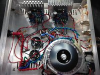
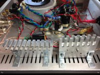
post661 pic3 shows a lot of tappings onto the second stage PSU Zero Volts (pulse charging) wire.
Are you using the PSU as your Main Audio Ground?
The ground wires can be seen in pic2 on the connector strip under the main power switch, at the end of the PSU.
see if you can run the "ground" wire from amp PCB to PCB via a short thick wire/strip.
The shorter the lower the inductance.
The thicker the lower the resistance.
A wide strip has lower inductance than a thick wire or group of wires.
Remember the flat wide "earth" straps often used to earth the automobile engine? H.Ott shows pics of something similar when "earthing" separate chassis to each other, specifically for this minimum impedance issue.
Each amp PCB needs to see minimum impedance to it's Main Audio Ground. This minimises the voltage drops for any shared currents using that common route.
a short low-z path also reduces EMI pickup since it is less of a "good" antenna.
another good EMI reduction practice is to keep low level signal lines away from other lines and when they must get near then have them cross at right angles or as nearly so as practicable.
another good EMI reduction practice is to keep low level signal lines away from other lines and when they must get near then have them cross at right angles or as nearly so as practicable.
Last edited:
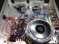
OK, here is the power supply wiring pictured, maybe it will make more sense. The ground taps are at the end of the PSU components, not sure if I should change anything,...? So far zero noise of any kind. Also, it is all silver in Teflon wire, so should be low resistance. I also have the standard radio filters on the AC line IEC connector (X/Y class caps).
Attachments
Last edited:
For 0v and grounding purposes, perhaps it would be good to buy some green insulated wire with solid copper conductor inside?
I am game if it makes a difference, I do have some laying around. What is in there now is multi-strand silver plated copper, about 18 AWG Teflon insulated.
OK, I would like more bass. The presentation is just a tad missing on the bottom half. I am going to a 1 uF from .47 uF input cap. I have polys...
Any other ideas?
Thanks.
FWIW i use a 3.3 panasonic poly or 5.6 uf solen on the input, mounting them and the input jacks inside a small dedicated die cast aluminum box. without the box their physical size makes for some noise pickup.
that said, those long circuitous 0v and rail leads may be a culprit.
the silver may give you low R but not low-z (i think that is the basis for the suggestions from andrew and daniel).
for a board-mounted chip i'd generally shoot for a max of 3 inches total from the chip power pins to a large reservoir (10,000 uf or more per chip per rail) and a total path between the reservoir and the trafo (including the bridge) of 4 inches.
with careful layout this is doable by removing cap height as a factor -- horizontal cap mounting on the floor of the cabinet. with point-to-point, even shorter paths are doable.
you may or may not hear a difference depending on the music and the speakers. with good speakers the lowest octave of a 5-string or 6-string bass is to me _very_ noticeably better with the lowest notes clearly retaining string character rather than sounding more like a drum. to me it is worth the trouble but to others it may not be worthwhile.
all this presupposes that the music source has not already corrupted fidelity.
Last edited:
Green for 0V cables, would make it a little easier to view the layout.I am game if it makes a difference, I do have some laying around. What is in there now is multi-strand silver plated copper, about 18 AWG Teflon insulated.
Solid copper is uncomplicated for DC powered audio circuits.
With audio amplifiers, more bass is achievable by decreasing midrange noise. Distortion/noise is easily audible at ear sensitivity peak, which is at the upper midrange.OK, I would like more bass. The presentation is just a tad missing on the bottom half. I am going to a 1 uF from .47 uF input cap. I have polys... Any other ideas? Thanks.
Some of the kits ship with decouplers that are far too small to support clear bass harmonics, so you could swap those out for one or two 220uF (or 270uF) caps per each rail.
For 0v and grounding purposes, perhaps it would be good to buy some green insulated wire with solid copper conductor inside?
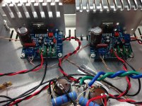
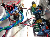
I had some solid core copper dark gray insulation, so that went in. You can see it there as the 0V feeding the boards.
Try 10uf for input and 100uf for feedback for more bass.")
A 4.7 uF and 100 uF FB cap went it. The 100 uF was necessary to make space for the bigger polys. Yes, more bass!
FWIW i use a 3.3 panasonic poly or 5.6 uf solen on the input...shoot for a max of 3 inches total from the chip power pins to a large reservoir (10,000 uf or more per chip per rail) and a total path between the reservoir and the trafo (including the bridge) of 4 inches...
4.7 uF poly went it, these are Dayton Audio, a good general cap. Also, shortened all wires.
With audio amplifiers, more bass is achievable by decreasing midrange noise. Distortion/noise is easily audible at ear sensitivity peak, which is at the upper midrange.
This is a very interesting point if you could explain a bit, thanks. I am always looking for more bass.
Appreciate all the input, I did not get to test it much yesterday, but so far there is definitely more bass coming through. I will test it later and report.
Attachments
Experiment: Add progressively more (identical models of) 100uF caps in parallel until you find out how much you actually need.... and 100 uF FB cap went it. The 100 uF was necessary to make space for the bigger polys. Yes, more bass!
That idea might be visually objectionable, but it probably sounds good.
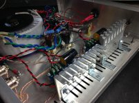
and they are too small anyway, you would probably be better off bolting those TDA to the case/chassis for heat transferIt looks like one of those heatsinks is loose.
and they are too small anyway, you would probably be better off bolting those TDA to the case/chassis for heat transfer
They are good and tight. With my type of use they barely get warm, but this is good idea for any future use with smaller speakers.
TDA7293 TDA7294 Amplifier is very good. HIFI.
They are cheaper than those of digital amplifier effect Is much better.
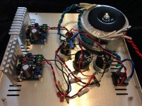
Did more listening with a friend over the weekend, and he agreed this is a very good amp. It is providing great bass, deep and low, and the highs are crystal clear with lots of extension. I know some will argue, but this amp would easily humble my gainclone and my other tripaths for that matter.
and they are too small anyway, you would probably be better off bolting those TDA to the case/chassis for heat transfer
I did just that, even though with my speakers, the heatsinks barely get warm.
Thanks for all the suggestions, this amp is a winner.
Attachments
Using TDA7293 with 3-way active speakers?
Hope this is not too off-topic, but I have read several posts in this thread that make reference to enhancing the Highs/Mids/Bass... I am planning to build a 3 or 4-way (not sure if I want to incorporate a Sub in the same box yet) using a L/R crossover to split the signal and route to separate mono TDA7293 boards within the speaker box. (sort of a parallel approach, but tackling different frequency ranges with each) All drivers will be 8-ohm. The Crossovers will be approximately this: Woofer to 300hz, mid between 300 to 4000hz Tweeter above 4kHz. Are there things I can do to optimize the output of this chip for these frequency ranges? (am testing several existing board options including a P2P option, which I plan to tweak based on Daniel's schematics from this thread)
Thanks very much in advance,
Sixto - Minneapolis.
Last edited:
- Status
- This old topic is closed. If you want to reopen this topic, contact a moderator using the "Report Post" button.
- Home
- Amplifiers
- Chip Amps
- Optimizing TDA7294 Output