P.S.
Thanks for the compliments. I wish I was trained as an engineer, but my calc skills are too poor and there's no nearby educational facilities for EE. Gosh I wish I knew how to use a scope. Making handmade tuners is a bit slow going without a scope. Oh the darned coils! But, as a benefit of a few wars with that, aligning already built tuners is super easy. It was really good practice for power filtering too.
I don't buy that for a minute. If you trained yourself to your level of proficiency then I have more respect for you than a run of the mill engineer. A lot of the stuff you do would be scoffed at by engineers, yet I can demonstrate in engineer-speak that you are correct. For example, I was talking about capacitors for audio with one of my colleagues and he laughed at me. Then I drew him a fancy engineering diagram complete with equations and he didn't even understand it, so he still dismissed it.
Engineers are trained to be purely objective. A good design incorporates both objective and subjective elements.
One of the guys here on this thread made the amplifier board power caps out of parallel 100u caps, and then stacked on enough until the tone leveled. I haven't tried that yet.
I get the picture. This is what I mean by objective and subjective elements being part of a good design.
Keep up the good work.
ADI - Analog Dialogue | Op Amp Applications Handbook
Section 7, "Hardware and Housekeeping Techniques", is quite relevant to this discussion. Figure 7-1 models a real world capacitor.
Section 7, "Hardware and Housekeeping Techniques", is quite relevant to this discussion. Figure 7-1 models a real world capacitor.
Thanks for your kind comments.Fast Eddie D said:A good design incorporates both objective and subjective elements.
Well, if you think my design ideas have merit, put capacitor located at speaker and series to speaker ground, kick on a bass booster, rock the house and parallel up capacitance size to whatever is needed for maximum benefit (filter size = speaker capacity), and turn off the bass booster. Then try to live without the caps.
For example:
The 96 db efficient speaker at top of this page: DeVORE FIDELITY Orangutan
Does 92db efficiency on a solid state amplifier or 96db from a tube amplifier's current drive. Amplifier cost too much.
Capacitor roll-off precision adjusted cause progressive current drive (bass is current drive), and if sized just right, I think you'll notice about 3db and some rockin clarity at lowest pitches. Lowest cost way to drive speaker correctly and kiss the plaster goodbye. See also Bob Cordell's website on speaker tuning, but the active circuit and brute force is unnecessary. A bit more tuning between speaker and capacitor will make bass booster unnecessary. Sealed box speakers are much easier though, and low pitch extension is available via progressive current drive. Orthodox with subwoofers (instead of only booming, you get real bass), actually works on any speaker. Why didn't someone tell me this?
Also compare successfully powerful Old 10 watt 1969 JLH amplifier with newer and supposedly more powerful New 15 watt 1996 reissue that failed because of less power. Oops!! Output cap. That charming phrase "define the audio band" regarding suitable passband for audio amp, not more not less? Apparently, that even works at amplifier output. Speakers don't require DC anyway.
For doing the job more streamlined, Engineer Susan Parker has a transformer arrangement that works even better for suitably driving a speaker.
Her plan is more than twice as effective as mine, by my plan has a higher "doable" aspect, and 1db~3db more at the speaker is still a suitable boost.
Other place for a similar boost is at the power circuit. Did that already.

Not yet fully optimized on this kit board. However, we have narrowed the parameters considerably.FOXYE said:There is electric scheme that works well with TDA7294/3?
The feedback resistor may be optimal in the range of 39K~82K.
The feedback resistor should be mounted directly to chip's pins.
The gain should probably be in the range of 25X~38X not more.
The feedback shunt RC requires big audiometric sizing for clarity. (especially with TDA729X)
You can try:
56k feedback resistor
440u+1.8K feedback shunt
(440u is parallel pair of Panasonic FC 220u)
47u bootstrap cap
Omit mute cap
22k input load
1u input cap
Solo 2u polyester rail to rail cap
Pair 220u amp board power caps
Further fine tuning or different design may be done to accommodate the needs of your speakers, room and ears or other AF receiver.
Last edited:
Very interesting, Daniel. And quite against the grain too.
It is true that a series capacitor provides a rise in bass response and a "hump" in the response at or near resonance. So tuning this capacitor can provide some optimisation of bass response.
Of course output caps provide additional benefits liks simple speaker protection and much less stringent requirements for DC stability of a circuit.
The caveats are obvious and the claims of "increased distortion" are worth consideration. Research by Doug Self and others has demonstrated that output caps introduce significant distortion well into the midrange and beyond. They can be the significant source of distortion in a well designed circuit.
This is not to say that you shouldn't always avoid them; it depends on your objectives. While designing amplifiers like the "Blameless" amplifier that reduce distortions by half a decade or more is highly virtuous and important, it is not always a realistic or desirable objective for every application. Circuits like the DoZ are much easier than Blameless for someone looking to learn, they are far more optimised than the old circuits that they resemble, and they provide very good performance. It is true that they leave half a decade to a decade of distortion reduction on the table, but we're talking thousands or ten thousands of a percent. The tradeoff is that they work great and do not require a lot of proficiency to understand and construct.
Unfortunately they tested the quality of their power circuit instead. I would disagree that it was well designed since it was indeed the cause of the distortion. Conversely, we have fine quality examples of split rail supply on this thread and the single rail amp test is not applicable at all. Perhaps you already have caps series to your midrange and tweeter for reducing distortion? See? It is okay to help the woofer and amplifier achieve lower distortion and greater efficiency by defining the load as "within the audio band."Research by Doug Self and others has demonstrated that output caps introduce significant distortion well into the midrange and beyond. They can be the significant source of distortion in a well designed circuit.
If using parallel crossover, you can also test ac coupled for woofer only, and series to + is a bit different than series to woofer ground. So, that needs explored as well.
For reference, auto center, passive rail split, etc. . . will stop the distortion in single rail amplifiers, without removing the output cap. Actually, the rail splitter approach can sometimes outperform real split rail. Not just talkin. Done it a lot. Mostly for small signal though, but a few times for a power amp. That phrase "define the audio band"? Yeah, it works for rockin bass. Really hard to believe the number of audiophiles and engineers alike listening to boomy distorted bass on account of cap phobia. That's just astonishing.
I brought this up because the softie limiter type in TDA729X will reduce bass at a certain point, so if we don't make unnecessary non-audio load, then the chip produces a lot more usable power (so far not past 127W). This is perhaps different than the brute force capacity/approach of discrete amplifiers where we can concentrate on causing as much x-max as possible rather than maximize the speaker.
P.S.
Oh a little caution: Output cap on single rail bridge amplifier may cause armstrong boost, which does happen to require stronger output devices and larger heatsinks. So, if the amount of amazement bass power exceeds +3db on single rail bridge, please check for overload conditions. Not a problem on this thread with TDA729X, but could possibly overheat the car stereo chip.
Last edited:
Oh sorry, so much and yet not enough. I've tested quite a few chips with ac coupled woofer (series composite cap), and LA4628 was allergic. However, the tripaths and philips chips worked fine and could be arranged for more headroom. I've ordered a hamburger priced TDA7297 to check it out, and all of my speakers have been upgraded to ac coupled woofer, so will find out if the little 15 watt ST chip likes it.
The TDA7294's have been running for years this way, so no problem there.
Very nice with flea power amplifiers. . . But not as noticeable with the TDA7294, since we already have a lot of headroom.
When it comes to capacitors, there's a few gaps in everyone's theories, including mine. So, could you check it out (with a split rail amp)?
Last edited:
Unfortunately they tested the quality of their power circuit instead.
I'm not convinced that this is true. It seems a trivial matter to isolate the capacitor distortion.
Perhaps you already have caps series to your midrange and tweeter for reducing distortion?
Well it certainly is true that if you didn't use a crossover you'd get distortion, but your claim seems like a misrepresentation of their effect.
It is okay to help the woofer and amplifier achieve lower distortion and greater efficiency by defining the load as "within the audio band."
This is an unorthodox view, but it is worthy of consideration for some applications.
That phrase "define the audio band"? Yeah, it works for rockin bass. Really hard to believe the number of audiophiles and engineers alike listening to boomy distorted bass on account of cap phobia. That's just astonishing.
It is a mindset, and the effect that you describe can offer a subjective improvement for reasons that can be objectively illustrated.
brought this up because the softie limiter type in TDA729X will reduce bass at a certain point, so if we don't make unnecessary non-audio load, then the chip produces a lot more usable power (so far not past 127W). This is perhaps different than the brute force capacity/approach of discrete amplifiers where we can concentrate on causing as much x-max as possible rather than maximize the speaker
This is a very good point that is ignored by virtually all contemporary designers.
P.S.
Oh a little caution: Output cap on single rail bridge amplifier may cause armstrong boost, which does happen to require stronger output devices and larger heatsinks. So, if the amount of amazement bass power exceeds +3db on single rail bridge, please check for overload conditions.
This is a blast from the past. Nobody thinks about this any more.
When it comes to capacitors, there's a few gaps in everyone's theories, including mine. So, could you check it out (with a split rail amp)?
It's worth a shot.
If you wanted to do that, it would be as simple as using two transistors, sources or emitters to the +/- inputs, with bias resistors to one rail, and collectors to the other. I would suggest something like the BC5xxC, MPSA18, 2N5089 etc. RC filter the collectors if the rails exceed Vcemax or if max dissipation is exceeded.
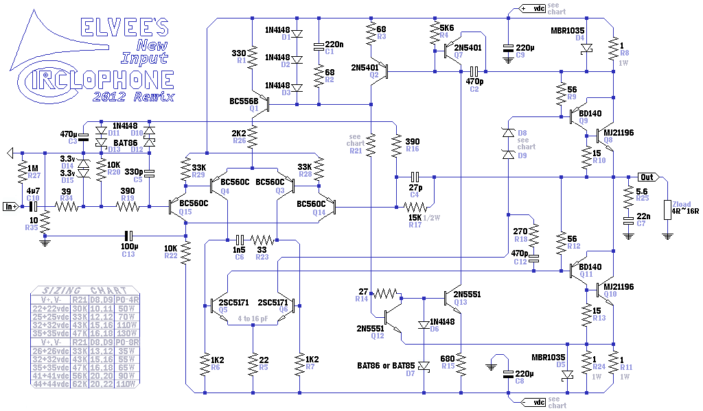
Ah, Kean's famous Srotsisnart Buffer! It fits chip amplifiers too? Wow, so much lower insertion loss and lower parts count than other solutions. Much less complicated than a chip based solution. Probably could fit it onto a dime size daughtercard to add atop the board. Of course I have almost no idea what component values or connections, except the clues in post#370 mention of LTP and power, and. . .
There is a schematic clue as well--Q14, Q15 on this Circlophone schematic.
Another tidbit of information that we do know: If your amplifier has limp bass because the source needs/lacks a buffer, then, in that case, a buffer will outperform an an equalizer, thoroughly. I think that adding the buffer could turn our nebulous 70 watts of something into a "safer bet" for level sounding audio. But, we need to decide before performing the labor fine tuning the amplifier's small signal area. Want a better bet with a buffer?
Yep, R28, R29, R22, Q14, Q15 and C13 are the components. Take these, and connect the emitters to the +/- inputs of the given amp, or chipamp. I don't know if this will improve the circuit in question but I think it's a good bet and Dan seems pretty sure, so it must be worth a try.
I agree. Check out this thread in this case:Let's not forget layout and wiring, Bob. Visually "small" design glitches can have big impact on the amp's perfomance additional to (if not even dominating) parts selection.
http://www.diyaudio.com/forums/chip...ons-tda7293-tda7294-lm3886-etc-available.html
Tiny size double-layer board avoids disaster layout from the mad pinout of the TDA729X, like this:
1pc x TDA7293 Mono Amplifier Board Official Standard 85 w Original B Board | eBay
I'd give those weak slippery screw terminals a fail because they're hazardous and reduce quality, and the components may be random values of bargain parts; however, the board itself looks quite good. SO, as soon as you de-solder those screw terminals, then you've got a non-disaster option available.
EDIT: Also found:
http://www.ebay.com/itm/TDA7294-65W-Mono-amplifier-board-Kit-28-/200912855861
There's the TDA7294 version, conveniently in kit form so you can put on the components you want to use.
Last edited:
Did you realize that the topic for this thread, is Not subwoofers?
Anyway. . .
To remove the mute, connect a 10k resistor from pin10 to pin7.
Power caps at/upon the amp board may be about 270u per rail.
Maximum transformer sizing is 200VA, and fuses are suggested.
The rest of the information is located here: TDA7294 Datasheet
However. . .
There are also good LM3886 Subwoofer Amplifiers, to consider.
More awesome. . .
Why not biamp for TDA729X mids & treble, with LM3886 bass?
Right. The bridge resistor should be same value as your feedback resistors.
For bridged and parallel applications:
Pin9 from one chip is cabled to the other chip, and Pin10 from one chip is cabled to the other chip. Not more parts than: 1 10k resistor for mute, 1 22k resistor for standby, 1 10u cap for standby, and 2 wires of course. The chips must operate mute and standby at same time, so you force that.
For more information, also see the TDA7293 datasheet (it has more clues).
Yes!Couldnt we take common resistor for mute pins
For bridged and parallel applications:
Pin9 from one chip is cabled to the other chip, and Pin10 from one chip is cabled to the other chip. Not more parts than: 1 10k resistor for mute, 1 22k resistor for standby, 1 10u cap for standby, and 2 wires of course. The chips must operate mute and standby at same time, so you force that.
For more information, also see the TDA7293 datasheet (it has more clues).
Last edited:
That's true!I think i need to parallel then coz bridging heats up a lot
Bridged:
If your speaker is 8 ohm and your amp is bridged, each chip sees a 4 ohm load, which reduces efficiency dramatically and sends a lot more power into the heatsink, and that gets hot. With two chips at twice the load, your heatsink would need to be four times bigger.
On powerside, you quadrupled the load, but it isn't safe to quadruple the transformer because you only doubled the number of chips and therefore may only double the transformer current. SO, this bridge amp idea operates starved for current, wastes a lot, and you've then got a big audio compressor with poor bass. In addition to those troubles, bridged adds an additional power amp to the chain, effectively doubling the amplifier distortion. And double distortion Plus straining outputs for much more distortion is audibly inferior. That is definitely not a home hi-fi, but it might make a fun and very loud guitar amp.
Parallel:
If your speaker is 4 ohm and your amp is paralleled, each chip sees a 8 ohm load. The number of chips is double, the transformer current may be double and the heatsink size is double. This all matches up nicely and works well.
The modern low inductance style speaker has a pair of 8 ohm woofers making a 4 ohm load, transducers in parallel has half LE, and the crossover coils are half size; and it is done with the purpose of a very clear and dynamic sound. These types are delightful to use with the Parallel chip amplifier. That plan effectively doubles the number of speakers and amplifiers, Without doubling the number of boxes and wires, and Without doubling the amount of strain on each woofer. With the parallel amp, the performance is usually excellent.
Basically, bridged makes a guitar amp, but parallel makes a hi-fi. Which one do you want?
Last edited:
- Status
- This old topic is closed. If you want to reopen this topic, contact a moderator using the "Report Post" button.
- Home
- Amplifiers
- Chip Amps
- Optimizing TDA7294 Output