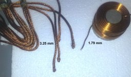
The inductor is too thin; however the braid will absorb the solder, turn solid and then steal all the heat out of your iron, thus taking a lot more time to do it. I tried this once--only once.O.K. I have the Romex, but checking the stash I found some bundles I've been hanging on to for years, and a salvaged inductor I can twist up several lenghts. Is there still an advantage/preference for just the single solid Romex?
") Well, I'd think you'd probably like the Romex best.
Well, I'd think you'd probably like the Romex best.I don't embarrass easily either, but this was really close: http://www.diyaudio.com/forums/head...d-not-earplug-headphones-buy.html#post3356886Hey Daniel, It's a good thing I don't embarrass easily.
P.S. How goes it with your Romex adventure? Most point-to-point and perfboard power supplies end up with the flaw of overrelance on cap pin length to make connections, so, instead, I'd like to suggest minimal pin length for all components. You're very talented, so I'm looking forward to seeing a nice sturdy power supply with good use of thick copper for low-inductance performance benefiting clarity and dynamics.
Bass peak power can be, momentarily, well beyond the normal wattage of a Class AB power amplifier, so a good means to promote bass slam is a sturdy-built power board that doesn't throttle/blur the bass peak, and TDA729x needs all the help it can get for passable bass clarity and it must have bass clarity before it can do anything else clearly. Oh my. So, I think that the sturdy copper and a rather powerful soldering iron can help.
The speaker signal is highly reliant on every connection at the power board, especially the 0v line, so I'd also like to suggest a double-strength/thick 0v line if that is doable.
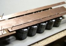
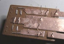
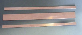
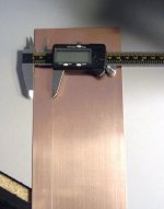
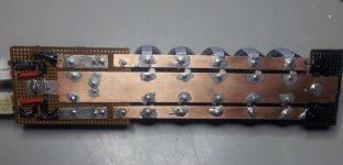
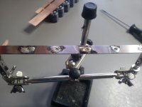
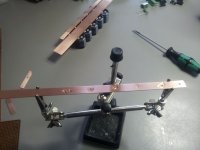
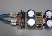
This is what I came up with. A quick trip to the local hobby store gave me the choice of real rails (brass HO train track stock ), solid brass tubing and a 6" x 10" x 1/32" solid copper flat stock ($6). The sheet reminded me of some pictures I've seen on the forum so I chose it for this version. I'm hopping copper is copper and this will perform the same as the Romex.
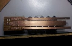
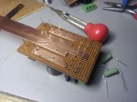
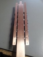
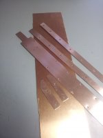
Strips were marked (22 mm & 8 mm), cut on a band saw with a temporary fence and cleaned up with a file and sandpaper. Some parts are mounted through hole and others will be bent and soldered. I couldn't find any perfboard long enough at the local RS so I used chunks from my parts drawer. May have to devise some additional support. The DC out will have the same green screw pads as the AC In. A little more layout and drilling and I'll heat up the soldering iron for pre-tinning all the joints and final assembly.
If you see something, say something.
), solid brass tubing and a 6" x 10" x 1/32" solid copper flat stock ($6). The sheet reminded me of some pictures I've seen on the forum so I chose it for this version. I'm hopping copper is copper and this will perform the same as the Romex.Strips were marked (22 mm & 8 mm), cut on a band saw with a temporary fence and cleaned up with a file and sandpaper. Some parts are mounted through hole and others will be bent and soldered. I couldn't find any perfboard long enough at the local RS so I used chunks from my parts drawer. May have to devise some additional support. The DC out will have the same green screw pads as the AC In. A little more layout and drilling and I'll heat up the soldering iron for pre-tinning all the joints and final assembly.
If you see something, say something.
Attachments
-
 DSC00922.JPG96 KB · Views: 174
 -
 20130205_201820.jpg458.8 KB · Views: 174
 -
 20130205_201009.jpg87.8 KB · Views: 185
 -
 20130205_200946.jpg105.5 KB · Views: 191
 -
 DSC00921.JPG113.5 KB · Views: 419
 -
 20130205_190459.jpg103.7 KB · Views: 428
 -
 Cuts.JPG63.7 KB · Views: 426
 -
 Copper Marks.jpg168.1 KB · Views: 447
Looks good bob. I was thinking of something very similar with the 0 volt connections as I have a piece of copper left over from the fe enclosure. I am thinking of using 12 awg for the +/- rails to keep the distances at a minimum and then cutting a piece of the flat stock copper to be equal to a 6 awg wire.(based off daniels recommendations ).
I really like your perf board layout, and the terminal blocks are such an obvious convenience, great idea.
I am interested to see how well/difficult it will be to solder to the copper sheet. Keep us posted.
I really like your perf board layout, and the terminal blocks are such an obvious convenience, great idea.
I am interested to see how well/difficult it will be to solder to the copper sheet. Keep us posted.
Thanks, I'm planning to scour the copper with Scotch-Brite, apply liquid flux and tin everything using a mini torch before final assembly with the soldering iron. I'll epoxy the copper to the perf-board first.
Attachments
Last edited:
Yesterday, I was wishing there was some way to steampunk a power supply. I was also wondering how to make the power supply compact instead of long and zigzag (happens when I try to "crowd" the caps to minimize distance to the 0v rail). Today, you taught me how to do both. Awesome. Thanks!
Possible errata:
I think there might should be a little bit more space between the rails so that you don't have to lacquer them for spark avoidance. Avoiding sparks usually takes about 1/4" space. But, if you're going to lacquer, that's good because it keeps perfboard from stinking when it gets hot (in this case, lacquer the top of the perfboard before mounting the caps). The wal-mart has black, white and clear Rustoleum spray Lacquer in stock in with the spray paint section. It hardens quickly. I'd use the clear lacquer on bottom, just in case you'd want to show off those big copper tracks.
Known hazard:
Those little green screw taps are known to loosen, slip incessantly, cause static and generally degrade both quality and safety. For power supply, you need euro type with big screws, not china type with little screws.
And,
In that layout of the bridge rectifier, you'll want to reinforce the insulation of your AC leads jumper from bridge rectifier to screw terminals with some shrink tubing just to give it some extra durability. The wire type used for jumper probably needs to be insulated solid copper so that it doesn't wander about.
Or,
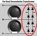
I don't use any screw connectors with mine but rather have little holes drilled through the perfboard in the right spots to connect the transformer cables directly. In my case, the transformer cables are inserted through the top of the perfboard so that the transformer cables don't criscross anything, and my cables are soldered securely. My transformer cables are bundled as 2 groups of twisted pair as is typical for dual secondaries transformers.
Generally, I like everything about your build except for the frightening miniature screw connectors. And man, those gotta go--they don't match your build quality.
Possible errata:
I think there might should be a little bit more space between the rails so that you don't have to lacquer them for spark avoidance. Avoiding sparks usually takes about 1/4" space. But, if you're going to lacquer, that's good because it keeps perfboard from stinking when it gets hot (in this case, lacquer the top of the perfboard before mounting the caps). The wal-mart has black, white and clear Rustoleum spray Lacquer in stock in with the spray paint section. It hardens quickly. I'd use the clear lacquer on bottom, just in case you'd want to show off those big copper tracks.
Known hazard:
Those little green screw taps are known to loosen, slip incessantly, cause static and generally degrade both quality and safety. For power supply, you need euro type with big screws, not china type with little screws.
And,
In that layout of the bridge rectifier, you'll want to reinforce the insulation of your AC leads jumper from bridge rectifier to screw terminals with some shrink tubing just to give it some extra durability. The wire type used for jumper probably needs to be insulated solid copper so that it doesn't wander about.
Or,
I don't use any screw connectors with mine but rather have little holes drilled through the perfboard in the right spots to connect the transformer cables directly. In my case, the transformer cables are inserted through the top of the perfboard so that the transformer cables don't criscross anything, and my cables are soldered securely. My transformer cables are bundled as 2 groups of twisted pair as is typical for dual secondaries transformers.
Generally, I like everything about your build except for the frightening miniature screw connectors. And man, those gotta go--they don't match your build quality.
Last edited:
the terminal blocks are such an obvious convenience, great idea.
....or not
A question though. I know when designing pcbs it is advised to avoid sharp angles when laying out traces, is there any use for that rule when shaping the copper plate traces here? Bob I noticed some of your corners were rounded, and was wondering if that was why?
What about fastons for power supply conections?
Hi Guys,
A bunch of good ideas. Daniel you sound just like Andrew and madisonears - they both hate those little green things. Don't have enough fastons so I"ll do something with euros. What I had was "usable" with the short piece of perf-board. I'll probably rework that part later when new board is available. I also noticed the PS could easily be done modular with three umbilical wires. Maybe next time.
I considered the space between the buses yesterday. I thought the only way I could increase it was to attach the pins to the edge of the copper, but after looking at it I see I had almost a 1/16" off center to play with and still have a full circle to solder.
There is a half sheet of the copper plate left so the next one will use all the suggested changes. Should be finished in a few hours and I post more pics then.
A bunch of good ideas. Daniel you sound just like Andrew and madisonears - they both hate those little green things.
Don't have enough fastons so I"ll do something with euros. What I had was "usable" with the short piece of perf-board. I'll probably rework that part later when new board is available. I also noticed the PS could easily be done modular with three umbilical wires. Maybe next time.I considered the space between the buses yesterday. I thought the only way I could increase it was to attach the pins to the edge of the copper, but after looking at it I see I had almost a 1/16" off center to play with and still have a full circle to solder.
There is a half sheet of the copper plate left so the next one will use all the suggested changes. Should be finished in a few hours and I post more pics then.
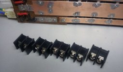
The surge of current delivered at startup and hopefully for bass beat too, is far beyond the safe capacity of most convenience connectors. We need something sturdy that doesn't degrade, spark or loosen over time.
There is a type suitable for power board use:
A barrier terminal block.

The metal plates under the screws are springy, maintaining a secure connection that doesn't loosen over time.
Mouser search:
Barrier Terminal Blocks | Mouser
These are sturdy enough to withstand the charging surges and peak current of a power supply board.
This looks like a good time to mention mains fuses--a fuse series to the transformer primary.
Seeing those dreadful little green blocks makes me annoyed, anxious, afraid and sad. Please remove them.
There is a type suitable for power board use:
A barrier terminal block.
The metal plates under the screws are springy, maintaining a secure connection that doesn't loosen over time.
Mouser search:
Barrier Terminal Blocks | Mouser
These are sturdy enough to withstand the charging surges and peak current of a power supply board.
This looks like a good time to mention mains fuses--a fuse series to the transformer primary.
Oh no! The lethal green blocks! The highest current area is an inappropriate place for the worst quality connection. They'll cause static, dump some bass power, defeat efforts for quality, burn up your amp, burn up your speakers, catch your house on fire, and kill pets and people. Worst quality ever!bcmbob said:Daniel you sound just like Andrew and madisonears - they both hate those little green things.
Seeing those dreadful little green blocks makes me annoyed, anxious, afraid and sad. Please remove them.
It could be good to have several millimeters more spacing between the rails. That center track could be reduced slightly in width, and a little adjustment is probably enough to avoid an erratic sparky noise or weird static. Remember that your signal does travel through the power supply, so that area is actually important to audio and it needs controlled/refined a bit so that we don't end up spending a lot of time chasing errata. After you do what you can to adjust the spacing, then you might consider spraying it with several coats of clear lacquer.bcmbob said:I considered the space between the buses yesterday. I thought the only way I could increase it was to attach the pins to the edge of the copper, but after looking at it I see I had almost a 1/16" off center to play with and still have a full circle to solder. There is a half sheet of the copper plate left so the next one will use all the suggested changes. Should be finished in a few hours and I post more pics then.
Due to surge currents involved, connections to and from a bridge rectifier need to be approximately twenty times stronger than a typical speaker connection. If you wouldn't use the dodgy little green blocks for speaker connectors, the matter is only twenty times worse at the power board. Quality control: Mail all of the green blocks back to China.
Audio Quality? Oops! We forgot the dials.
I just thought of it. We forgot to snub the secondaries for audio quality. Instead of those little green blocks, you can install Kean's 50R trimmer + 2u polyester cap (variable RC to snub the secondaries) at that location.
And Thanks!! I was wondering how to get the trimmer at the bridge rectifier without overheating the trimmer, but the jumper that you showed in your photos will drop the heat so it doesn't melt the trimmer.
Last edited:
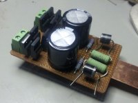
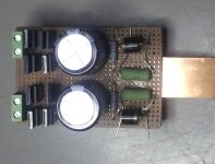
Well, It's close but no cookie. In short - no explosions or stinky green smoke. The PS works but the values are not correct. I'll just run through the photos.
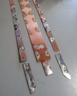
Copper pieces cleaned and scuffed.
Strips fitted on caps. Could have drilled closer to the edge.
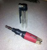
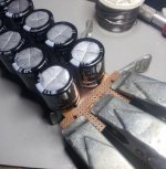
Tinning process.
DC end fastened with epoxy.
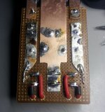
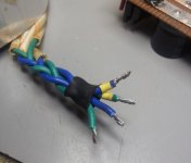
Solid Cardas jumpers installed.
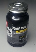
Insulated with Liquid Tape. Probably on all copper when finished.
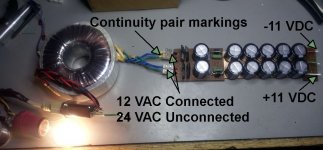
Identify AC#1 and AC#2.
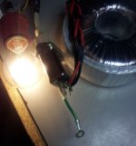
Hook-up.
So the first problem was the bulb tester didn't go all the way down. My temp gun showed no component above ambient after three minutes of operation. The first DC output check showed a range between 9 - 11 with constant fluctuation.
I went back to the AC end and found both rails read 12 VAC. When disconnected they are 24 on both.
Now here is where it's good I don't get embarrassed easily. When soldering the caps I reversed the orientation (should have stood on my head) compared to the diagram. To avoid de-soldering, I reversed the diodes - meaning the marking ring on the negative rail pointed back toward the AC end, and the positive installed toward the DC end. Although the PS is working (kinda) the polarities are reversed. The relationship between the diodes and the rectifiers may be more complicated that I assumed.
All in all I'm pleased with the progress so far but,
Help Daniel !!! Get me out of this
Copper pieces cleaned and scuffed.
Strips fitted on caps. Could have drilled closer to the edge.
Tinning process.
DC end fastened with epoxy.
Solid Cardas jumpers installed.
Insulated with Liquid Tape. Probably on all copper when finished.
Identify AC#1 and AC#2.
Hook-up.
So the first problem was the bulb tester didn't go all the way down. My temp gun showed no component above ambient after three minutes of operation. The first DC output check showed a range between 9 - 11 with constant fluctuation.
I went back to the AC end and found both rails read 12 VAC. When disconnected they are 24 on both.
Now here is where it's good I don't get embarrassed easily. When soldering the caps I reversed the orientation (should have stood on my head) compared to the diagram. To avoid de-soldering, I reversed the diodes - meaning the marking ring on the negative rail pointed back toward the AC end, and the positive installed toward the DC end. Although the PS is working (kinda) the polarities are reversed. The relationship between the diodes and the rectifiers may be more complicated that I assumed.
All in all I'm pleased with the progress so far but,
Help Daniel !!! Get me out of this
Attachments
Oh, my. Well, you're going to want to de-solder all of those caps anyway because you need an insulator (like some perfboard or fiberglass board) between the cap and the metal rails. The cap bodies are aluminum and their label is very thin, and although I'd like to offer a quick fix, there isn't one.
After you turn the caps around, you need to remove and check the health of the 0.25R to see if they're not open circuit. And you need to remove the 6a standard diodes.
Leave the 0.25R and 6a off until you check out the bridge rectifier and first caps (this step is checking the power supply with just the first two caps active).
Next connect the 6a diodes and check the rest.
Lastly, reinstall the 0.25R.
Kudos for using the bulb tester!
Bummer Bob. Since you have some re-working to do I was thinking it may simplify things for you if you were able to lay all of the components out on one board. If you google the phrase fr4 sheet you will find many vendors of large blank fr4 sheets. It is fairly reasonably priced too. Doing a quick search I found green, natural and black, im sure some digging might produce some fancier colors.
Keep at it Bob.
Keep at it Bob.
Oh, my indeed.
As soon as my head hit the pillow I realized I had not done a full inversion. The rectifier flow pics you posted popped into my head.
I almost stopped construction yesterday to wait for more perfboard for a related but slightly different reason. That center plate is so large that even the heavy duty iron and the tinning weren't enough to overcome the heat dissipation. I gave it an assist with the torch on low, which made me think I might be burning that thin paint on the caps. Should have had the sense to push the "hold" button there - but you know how how we "kids" are.
After the dis-assembly and forensics I might remove some of the metal at the center of the large plate. Your report of shuffling the caps to remove the zig-zag placement prompted me to think of an elongated Romex doughnut as a solution. I might apply the idea with this flat stock.
I'll be placing an order at Mouser later this morning and might buy both fiberglass and paperboard. I'll add a couple one piece rectifiers also. I already have duplicates of everything but the caps as I doubled the component count on the original PS parts order.
The credit for the bulb tester has to go to Andrew T. He's got me convinced I need one even if i'm just plugging in my electric toothbrush.
I'll continue Saturday when the parts arrive.
Mr. 4X4, I will search for that and hopefully Mouser will carry the product.
I forgot to answer your question about the curved edges on the plates. That was just to gain a little clearance, but I did try to soften the corners (rather inconsistently) where I could to lessen the possibility of a spark jump.
Thanks for your encouragement.
As soon as my head hit the pillow I realized I had not done a full inversion. The rectifier flow pics you posted popped into my head.
I almost stopped construction yesterday to wait for more perfboard for a related but slightly different reason. That center plate is so large that even the heavy duty iron and the tinning weren't enough to overcome the heat dissipation. I gave it an assist with the torch on low, which made me think I might be burning that thin paint on the caps. Should have had the sense to push the "hold" button there - but you know how how we "kids" are.
After the dis-assembly and forensics I might remove some of the metal at the center of the large plate. Your report of shuffling the caps to remove the zig-zag placement prompted me to think of an elongated Romex doughnut as a solution. I might apply the idea with this flat stock.
I'll be placing an order at Mouser later this morning and might buy both fiberglass and paperboard. I'll add a couple one piece rectifiers also. I already have duplicates of everything but the caps as I doubled the component count on the original PS parts order.
The credit for the bulb tester has to go to Andrew T. He's got me convinced I need one even if i'm just plugging in my electric toothbrush.
I'll continue Saturday when the parts arrive.
Mr. 4X4,
I will search for that and hopefully Mouser will carry the product.I forgot to answer your question about the curved edges on the plates. That was just to gain a little clearance, but I did try to soften the corners (rather inconsistently) where I could to lessen the possibility of a spark jump.
Thanks for your encouragement.
Attachments
Last edited:
- Status
- This old topic is closed. If you want to reopen this topic, contact a moderator using the "Report Post" button.
- Home
- Amplifiers
- Chip Amps
- Optimizing TDA7294 Output