Actually, even with a 3.3u film cap I can't get rid of the lower resonance. Now it's at 2.5KHz instead of 5KHz. So I'm afraid it may take a 10u lytic. I think this is what it would take. Unfortunately it takes a bit more planning to keep things from exploding or catching fire, or generally smelling.
Jay, the TDA7294 has a parasitic diode from output power pins to frontend power pins. Is it possible your Vs supply has higher voltage and so is heating up the package and tripping thermal protection?
I used same voltage for both power pins. And it is not hot at all. And I have the other channel next to it using same external power supply, and I can compare with the working channel if something is accidentally shorted.
I have 100n installed on input power supply pins to ground. I will remove them to see if they shorted anything.
Will reduce the value of mute resistor also. It was new, and I always measure resistors before soldering, so it can't be broken.
Hope the chip is fine.
I feel so stupid. I've been doing this by trial and error when I could just calculate the right snubber and be done with it. Only now do I understand Gootee's confusion. What's wrong with me? It was fun hearing how it changes the sound though.
<GRIN!>
(It's alright. I've been right there, too, more than a few times.)
I had an interesting (weird) case, not long ago, when I was trying to simulate a power supply, with LT-Spice. I was using a transformer model that included the windings' resistances and inductances, from actual measurements. At first, I had some significant ringing; basically it was breaking out into oscillation for a portion of each cycle. And it was at a fairly-low frequency (can't quite remember, but certainly below 1 MHz, and, I "think", below 100 kHz). But WOW it made the simulation run SO SLOWLY!
I looked up that snubber-design procedure again, dutifully step-swept capacitor values until the frequency was halved, then calculated the inductance and the characteristic impedance. It turned out to be something like 58k Ohms! I tried the calculations again and it came out the same, so I stuck a 58k resistor across the secondary, and figured no capacitor would be needed. BAM, the ringing was completely GONE.
Let me describe my test setup. My signal generator is a Tektronix FG504. My scope is a Tektronix 465B. Neither are in great condition but they work. I blew the internal fuse on my FG504, which I cannot find a replacement for, so I replaced it with a carbon comp 3.3R resistor. Coax termination and attenuator calibration may be slightly off, but it's still flat within the audio band.
<snipped>
Did you try looking at Sphere Research's website? I think they are in or near Vancouver, BC. Walter Shawlee is or was the owner and was always very helpful. He has TONS of Tek parts. Also, Deane Kidd might still be alive and might still be on the TekScopes group, at yahoogroups.com. He had a HUGE stockpile of NOS Tek parts, that he bought from Tek when they would quit making stuff. He is a former Tek employee.
Or, if you have a photo and/or specs for it, I might have one. I used to refurbish quite a bit of Tek gear and still have a lot of "stuff" here. I might even have an FG504 parts unit... I guess I might have the service manual too. But it would probably be quicker if you had the data on the fuse.
Which TM50x mainframe do you have for the FG504? I used to love the TM50x-based plug-in systems (and still do). I still have some, for calibrating oscilloscopes; TG501(?) time-mark generator and SG50something leveled-sine generator (the one that only goes up to 500-something MHz), and several other TM50x mainframes that are not being used. I still have about a hundred 7000-series scope plugins, too, and a bunch of mainframes for them (and a whole bunch of other stuff). I did manage to keep a nice 2465 scope and some good probes for myself. But the internal battery is dead right now, and then it will need to be recalibrated. But I have a 7904A and a 2235 that I can use until that gets done, and "several" lesser ones.
[P.S. I am no longer in the business of selling ANYTHING (except for my time, to my employer; after 24 years I finally got "a real job" again, about five years ago)]
Last edited:
Hey Gootee! I was quite interested in the Tektronix internal circuitry, and I've looked at the manuals and especially schematics for all the Tek stuff I own:
Tektronix 561B with 3A9 10uV diff amp (!!!) and 3B4 timebase.
Tektronix 465B which I had to do slight repairs on.
I measured the supplies on the FG504 and found some heavy sag synchronized to ripple. I took the FG504 out and measured the TM504 supplies but they were fine. I've checked tantalums on the FG504 but none of them are hot, but the problem I DID have was that the ceramic 100n SMD caps at the output buffer had become leaky and were bringing the supplies down - unusual problem! It still has the frequency wander/rail problem though and it may be the TM504 but it doesn't seem so. The fuse is a 300mA type in a cup shaped clear plastic case, and seemed to be designed for low ESL. This is why i used a carbon comp resistor; film resistors are very tiny coils. I wonder if there is a 1/4W resistor-size 300mA fuse available?
What would be really nice would be a spectrum analyzer - then I could really get down to figuring out a lot of things with real circuits.
I'm subscribed to the Tektronix yahoo group and visit the Sphere surplus site often. I've slobbered over their mystery grab bags but never had the opportunity to get one. Likewise for some of the test equipment.
Also, for the trafo probe I found a parallel resistor worked better for damping the scope+inductor resonance. It was an impulsive thing at first, so I just threw it together as quickly as possible to make it work. The series resistor makes the probe vulnerable to static interference. The resonance was at about 200KHz and I used a 2.8k parallel resistor to damp it.
As for cap concerns, a snubber with a 2.2uF film cap and 1/4W 50R trimmer is dissipation safe at anything under 90Vrms secondaries. This can be used for finding the right snubber value, potentially by ear even. I recommend a multi-turn trimmer or a pot, since my single-turn trimmer is a bit too touchy to adjust blind.
I think it may be my mains filter causing the resonance. I calculated the inductance and entered the values into simulation but there is something missing because the simulator doesn't predict the very low R value needed.
Last edited:
What kind of transformer model are you using? I.e Does it include any parasitics? In the "power supply reservoir size" thread, we made a scalable spice transformer model, with winding leakage inductances and resistances. It's included in a spreadsheet I posted, a few pages from the end of the thread. An earlier version of it is also in a .asc file I posted in the same thread. You need to download it. The spreadsheet is neat, too. It simulates a power supply; actually solves the differential equations numerically and produces plots that match ltspice. There's some novel vba code in it, too, for zooming and measuring the plots, like ltspice can.
gootee,
Your spreadsheet is exactly what I was hinting at in post #233. That's is excellent (pun intended) work. I haven't figured everything out yet but it is fantastic for those of us who are just learning the subject.
Thanks Bunches
BTW: I'm running it on OpenOffice and it appears to translate perfectly.
Last edited:
Gootee, I don't have the parts to replace all the lytics though I would if I could. Instead I tried to identify any failing ones. I cut one lead and measured with the resistance meter and got several Mohm or so. Actually I might or might not have discovered one was leaky but it's moot because I don't have any caps to replace them with (big caps!). I think I did check ESR but found they all measured normally.
I just modeled a series LC resonator. I have actually modeled the whole system before, including the line filter.
I just modeled a series LC resonator. I have actually modeled the whole system before, including the line filter.
gootee,
Your spreadsheet is exactly what I was hinting at in post #233. That's is excellent (pun intended) work. I haven't figured everything out yet but it is fantastic for those of us who are just learning the subject.
Thanks Bunches
BTW: I'm running it on OpenOffice and it appears to translate perfectly.
Thanks, Bob. Thre's also a PDF of a paper I wrote about it, which describes the analysis and the methods used, and also includes more about how to use the spreadsheet. It's at:
http://www.diyaudio.com/forums/power-supplies/216409-power-supply-resevoir-size-166.html#post3279883
It turns out that analyzing a simple transformer/rectifier/capacitor circuit is surprisingly complex, and there is no closed-form mathematical solution.
It was actually my first Excel macro and my first VBA programming experience (but I've programmed plenty, in other languages). The only code that I lifted from someone else is the mouse-drag zooming of the plots. But I came up with the mouse-cursor waveform measurement functionality and programmed that myself.
Still, if you really want to simulate that type of stuff (and any other circuits), I strongly recommend taking the plunge and downloading LT-Spice, from linear.com (It's free!). It's much easier in the long run, and much more powerful and flexible right away.
Regards,
Tom
Hey Tom,
I was going to ask for a walk through of the spreadsheet but as usual you were a step (several steps) ahead. I'm re-reading all the Rod Elliot PS related pages, but this time I'm taking the advice from that old book "Dinetics". Mr. Hubbard says you will never understand what you are reading if you skip over a single word you don't understand. Well, my Google finger is getting sore, but I'm having a lot of those "Oh, that's what they were talking about" moments.
Keantoken's tutorial on LT-Spice is also something many of us have needed. I have had the program installed for months but was very intimidated at jumping in.
Thanks again to all on the diyAudio Forum for such useful direction, patience and understanding to bring we less informed/experienced up to speed.
Last edited:
Not much going on (too busy) but some progress in the supply evaluation (the planned local decoupling scheme), see here : http://www.diyaudio.com/forums/power-supplies/226070-network-analyser-measurements.html#post3331935. I hope I'll finally build the full proto this weekend....
Those measurements are very encouraging and an array on a real PCB might measure even better.
I'm guessing that the exact feed and measurement point locations might have a significant effect. I think that Terry Given guessed that the mid-points of opposite sides of a square array would be good, for the input and output points, based on trying to get the current to spread across the board so that the caps shared it more-equally (although with a square array I can't understand it very well). I would have guessed that a circular or octagonal array would be good.
I'm guessing that the exact feed and measurement point locations might have a significant effect. I think that Terry Given guessed that the mid-points of opposite sides of a square array would be good, for the input and output points, based on trying to get the current to spread across the board so that the caps shared it more-equally (although with a square array I can't understand it very well). I would have guessed that a circular or octagonal array would be good.
Board came in
I really like like Kean's idea, post 240, and will try it as soon as I get a 50 ohm multi-turn trimmer (to use as variable resistor).
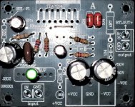
The TDA7294 ebay kit, same board that Bob is using, has arrived in the mail.
My first first steps included, simplify the mute circuit for power/midrange quality, use audiometric size NFB cap for bass quality, increase the 22u bootstrap cap to 47u for bass quality, and. . .
At first, it looked possible to set the feedback resistor closer (as in the photo below); however, this is still out on the end of a long thin trace shared by the bootstrap cap, the long thin trace is inductive and running maximum gain for non-audio signal is poor design. So, actually, the feedback resistor needs moved trackside, to directly under the chip from pin 2 to pin 14.
I really like like Kean's idea, post 240, and will try it as soon as I get a 50 ohm multi-turn trimmer (to use as variable resistor).
The TDA7294 ebay kit, same board that Bob is using, has arrived in the mail.
My first first steps included, simplify the mute circuit for power/midrange quality, use audiometric size NFB cap for bass quality, increase the 22u bootstrap cap to 47u for bass quality, and. . .
At first, it looked possible to set the feedback resistor closer (as in the photo below); however, this is still out on the end of a long thin trace shared by the bootstrap cap, the long thin trace is inductive and running maximum gain for non-audio signal is poor design. So, actually, the feedback resistor needs moved trackside, to directly under the chip from pin 2 to pin 14.
Attachments
Here's some options that don't have a bass blocker effect:
150u with 3k3 fs and 68k fb, 22x gain
220u with 2k7 fs and 75k fb, 29x gain
220u with 2k7 fs and 68k fb, 26x gain
220u with 3k3 fs and 75k fb, 24x gain
220u with 2k7 fs and 56k fb, 22x gain
270u with 2k2 fs and 68k fb, 32x gain
270u with 2k2 fs and 56k fb, 27x gain
270u with 2k7 fs and 68k fb, 26x gain
270u with 2k2 fs and 47k fb, 22x gain
330u with 1k8 fs and 56k fb, 32x gain
330u with 1k8 fs and 47k fb, 27x gain
330u with 2k2 fs and 56k fb, 26x gain
330u with 1k8 fs and 39k fb, 23x gain
470u with 1k2 fs and 33k fb, 29x gain
470u with 1k2 fs and 27k fb, 24x gain
470u with 1k5 fs and 33k fb, 23x gain
How,which formula you are calculating,
At 1K,22k,what value will be for cap? ,At 220uf,1K,,what will be feedback R?
Thanks.
Last edited:
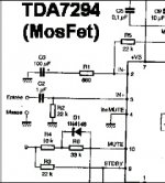
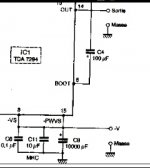
This schematic looks awesome
michel.terrier.pagesperso-orange.fr/radiocol/detail/tda7294.htm
Isn't that just extracts from the datasheet translated into French? Or am I missing something?
Isn't that just extracts from the datasheet translated into French? Or am I missing something?
there is a diagram near the default pic.just that.unable to reproduce the full image.
Attachments
Last edited:
- Status
- This old topic is closed. If you want to reopen this topic, contact a moderator using the "Report Post" button.
- Home
- Amplifiers
- Chip Amps
- Optimizing TDA7294 Output