Hi DIYAudio community
I want o build the lm386 with bass boost but i am not that knowledgeable about building pcb...
I got a chance to spend a few hrs with eagle software and the attached images are what I did.
Is the RED lines correct. I suspect that they are too close. they are negative traces. one for input(-) and the other for output(-).
if they are incorrect can someone please help me place them correctly.
and btw what exactly does a Bypass cap does in this circuit, if used. I noticed the line is not solid. will it help reduce noise? i know that the basic description is to bypass current but please forgive my ignorance. if it helps what cap value would you recommend.
sorry if I'm asking for too much.
thanks for your help
images are from eagle software
Attachments
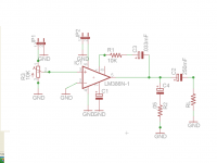
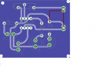
U have designed it like an RF circuit. The ground plane is unnecessary. Make the tracks bigger, and the components to be laid closer. Smaller the better. That 10K is a volume control, so find a potentiometer and fix it on the edge physically so that u can fix a knob for controlling the volume.
I don't know what u r going to hear with a 400mW amplifier...Your mobile has a more powerful amp nowadays.
Gajanan Phadte
I don't know what u r going to hear with a 400mW amplifier...Your mobile has a more powerful amp nowadays.
Gajanan Phadte
Thanks for the help.
I know its a weak ic but I just want to proof concept with it. If I can make this work then I'll jump into deeper waters. lol
btw how about the grounds from jumpers, line in and line out aren't they too close.
got it revised.
I know its a weak ic but I just want to proof concept with it. If I can make this work then I'll jump into deeper waters. lol
btw how about the grounds from jumpers, line in and line out aren't they too close.
got it revised.
Attachments
Last edited:
Proximity of tracks does not matter in such simple circuits.
First, there has to be a capacitor of about 100mfd and rated for more than dc supply, across the V+ and ground close to where the power enters the board. The point where ground is connected to this filter capacitor has to be used as star ground point. Your input ground connection has to reach this star without any other branching.
If u r going to etch this pcb yourself, avoid tracks between the IC pins as it is nearly impossible to etch by DIY methods unless u use photograhic method.
The R3 should be a potentiometer.
Gajanan Phadte
Last edited:
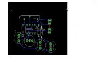
I got it redone. If I understood your instructions well. hopefully this one is ok for etching.
I will be using the laser toner/ ironing the copper clad method I saw on the net.
I know the trimpot is not ideal but when I tried using the regular pot from software it did not wanted to connect to the tracks somehow (I'm a noob I guess).
as you can see although a bit messy. I got C5 at the IN and VS.
from Vs goes to Pos cap and to IC# 6 pin. then NEG from IN and to Neg Vs together. I did the best I could. Had to vias pin 2&4.
thanks for your support
Attachments
Maybe this one is fine, didn't check all connectivity, but I suggest you use much thicker tracks.
These seem to be 10 or 12 Mil ; for home etching use at least 30 Mil, and in many places you will be able to go to 50 Mil ... and for ground use 100Mil if possible, "thinning" only when absolutely necessary.
Also enlarge IC pads or even better use "IC" pads, the rounded rectangle ones, and make pin 1 a full rectangle.
Or draw a small dot by it, to avoid mounting the IC the wrong way, by mistake.
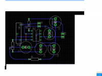
As an example, here's the PCB of my 12V 60W MosFet amplifier, used in battery powered Guitar/Bass/PA combos:
These seem to be 10 or 12 Mil ; for home etching use at least 30 Mil, and in many places you will be able to go to 50 Mil ... and for ground use 100Mil if possible, "thinning" only when absolutely necessary.
Also enlarge IC pads or even better use "IC" pads, the rounded rectangle ones, and make pin 1 a full rectangle.
Or draw a small dot by it, to avoid mounting the IC the wrong way, by mistake.
As an example, here's the PCB of my 12V 60W MosFet amplifier, used in battery powered Guitar/Bass/PA combos:
Attachments
You produced a short between pins 5 and 6.
Check if the trimmer is mounted in a way that clockwise turning increases the volume. Are you sure you want to need a screwdriver each time you adjust the volume? And you want to scratch C1 with the screwdriver every time?
You should use the correct values. You need µF not mF for the capacitors. The smaller values are nF instead of 0.0xx µF.
Although they may not influence the function, looks are also important. Try to align components where possible, e.g. C2 and C3 vertically, C1 and C4 horizontally. Space things equally, e.g. make the distance between C1 and C4 the same as between C4 and C2.
First of all however use the correct packages. C1, C3 and C4 will not be electrolytic capacitors. C4 should be a ceramic or film cap, C1 and C3 film caps. They have different shapes and sizes and that will make it easy to improve the layout. Try to move components around until you have the shortest possible paths everywhere.
It looks like components were selected for function only. Acceptable if just doing simple design and simulation, but when it comes to PCB layout dimensions really matter; you could say it's all that matters.
In this case using the correct packages should make the layout much easier.
In this case using the correct packages should make the layout much easier.
re: gmphadte. lol I know how a pot looks like, I even have some laying around. the only reason I used that element was because when I tried the regular pot element(item from the software library) I was unable to make the connections to be recognized in the pcb window. I had it hooked up and everything(schematic window) but somehow It would not show over the pcb window.
Re: sofaspud
you are absolutely right, I was trying to learn how to use the software and got a bit carried away. lol. the resistor I picked up I know nothing about the correct number to match the ones I got from Radio shack. I know they are 207 or 210, package. I really need to learn which is which when it comes to the right element to select. the lm386 was easy to pick lol, its hard to miss that one.
I know I might end up using some jump wires to make up for either the hole placement on the pcb print and the actual size of the hole on ther board compared to the actual elements.
thanks for all your help.
- Status
- This old topic is closed. If you want to reopen this topic, contact a moderator using the "Report Post" button.
- Home
- Amplifiers
- Chip Amps
- building a lm386 bass bost help