Philfr;3290487......... @ csom said:Thank you Phil,
I just followed the super simple Pcb Layout from the datasheet as ,for me, it is more convenient and compact than a point to point build. I can easily experiment with /replace parts of the amp.
I wanted to use LM1875 but due to nonavailability, I used TDA2050s with dual supply and they are great sounding too.
The quick PCB-making process, etching, along with the soldering of the components took me approximately less than 6 hours for 4 amps due to the simplicity of the circuit.
Last edited:
Thank's Mooly, I note your comment..
So it looks good for the future
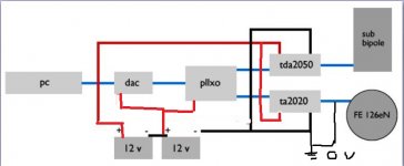
At this time I want shaw you a complete schematic of full system, to see if nothing was wrong about supply :
I've redrawn it for a single rail.
1. The batteries provide a 24 volt supply for the TDA's
2. The "lower" or righthand battery negative terminal is our zero point and is audio ground.
3. If the DAC etc need 12 volts then this must be fed from the lower battery. That provides a plus 12 volt rail above "ground"
4. A better ? approach might be to have a 12 volt regulator feeding the DAC. The supply for the 12 volt reg wouldbe from the plus 24 volt supply (the plus on the left hand battery). Doing that also "equalises" the load on the batteries so one doesn't discharge quicker than the other.
5. The signal must be AC coupled throughout. I've assumed the blue line is signal and the ground and so thats why I have showed the blue "ground" joined to the black negative battery terminal.
Attachments
Hi Mooly,
Sorry my drawn was not very clear..
Yes, blue line is signal (left and right channel).
pllxo (passive line level crossover) don't need supply.
TA2020 works only with 12 v dc
Thank's for coupled signal with ground, I forgot this.
"discharge quicker than the other", it's not a big problem, with one 18 amp gel battery I can use TA2020 and dac during about 30 hours, I hope 15 hours with tda's and two baterries..
Here's my tiny single supply monoblock. I built it to work with a 30 volt power brick from an old HP inkjet printer. It makes 16 watts before clipping into 4 ohms. With a 38 volt supply, I get 27 clean watts, but I'd have to use a fan to cool the small heatsink, so I stay 30 volts or less. I can even run it at low power with a 9 volt battery pack.
Here is my TDA2050 BTL amp. It makes 46 clean watts into 8 Ohms with my 38 volt supply. It is a split supply, but the amp could be made for single supply use easy enough. It is very small, but needs the large heatsink or a smaller one with fan.
On all my circuits, I use close to chip decoupling, star ground and RF filter on the input. They sound fantastic!
An externally hosted image should be here but it was not working when we last tested it.
Here is my TDA2050 BTL amp. It makes 46 clean watts into 8 Ohms with my 38 volt supply. It is a split supply, but the amp could be made for single supply use easy enough. It is very small, but needs the large heatsink or a smaller one with fan.
An externally hosted image should be here but it was not working when we last tested it.
An externally hosted image should be here but it was not working when we last tested it.
On all my circuits, I use close to chip decoupling, star ground and RF filter on the input. They sound fantastic!
I redraw schematic with version A and B, I'am not sure about signal ground 
An externally hosted image should be here but it was not working when we last tested it.
An externally hosted image should be here but it was not working when we last tested it.
I redraw schematic with version A and B, I'am not sure about signal ground
Nope
You can't do it that way. Your drawings show one TDA running on 12 volts and the other on 24 volts. For single rail all the grounds must use the right battery negative terminal.
First question. Will the TDA 2050 be constructed to use a single 24 volt rail or a dual -/+12 volt rail
Lets build it up from that.Thank's Mooly..
Yes, yes I see the problem
Solutions :
1 buy a new 12 volt battery just for TA2020 and dac
2 build another TDA2050 for drive FE126eN
This requires reflection !
Actually its my mistake... sorry.
I thought you had two TDA2050's in the diagram and not a TDA and the 12 volt TA2020. So diagram A of yours is correct. A case of seeing what you expect to see and not what is there
So.............
The TDA runs on 24 volt.
The TA runs on 12 volt.
They and all the audio grounds share the same ground point on the negative terminal of the same battery.
That still leaves the problem of unequal current draw on the batteries.
A 24 to 12 volt "linear" regulator is easy to arrange but is inefficient at high current compared to a switching regulator. The switching regulator would be more complex and unless built from a suitable kit or bought "off the shelf" would, I suspect be beyond what is realistically achievable.
Your suggestion of two TDA amplifiers both on 24 volt seems the easiest and actually "best" solution. A simple linear 24 to 12 volt regulator for the low current DAC is easy, just one three legged chip and a couple of caps.
Hi Mooly;
no problem..
So schematic A was good, another idea is to use two different batteries.
Left (on schematic) at 18 Amp/h and right at 24 Amp/h for example. That compensate the differences in uptake.
The TA2020 works starting from about 200 hz, and it's don't need high power.
I would have estimated the two power required to calculate value of batteries..
The dac (Musical Fidelity VDAC 2) require only 500mA..
Its OK for the power amps but the DAC needs to run off the other battery so that the grounds are correct.
Using different capacity batteries is OK in theory except you'll never come close in reality to equalising the discharge.
Does the DAC actually draw 500ma internally or is that just a marking on the box somewhere indicating an mains adapter rating etc ? I couldn't find any info on how that model DAC is powered
Thanks.
The specs say a 12 volt 500ma PSU is used. The DAC won't draw exactly 500ma, in fact it probably draws somewhere nearer 150-200ma at a guess. That's something you could measure for real but if you do use a battery then make sure you get the polarity correct. Check check and check again
The specs say a 12 volt 500ma PSU is used. The DAC won't draw exactly 500ma, in fact it probably draws somewhere nearer 150-200ma at a guess. That's something you could measure for real but if you do use a battery then make sure you get the polarity correct. Check check and check again
"Check check and check again"
Yes, with trial and error, my best way !
Maybe I can use a small battery or NiMh accumulators for only dac.
Wait and see after buiding the amp's.
Now I still have a lot of work to do :
finish enclosures for Fostex fullrange
rebuild pllxo for adapt new impedance
listing the part for TDA2050
build TDA's
You are over over over thinking.
Build a +/-12V supply with 2 12V batteries in series, the centerpoint is ground.
Use a DPDT switch for on/off.
Feed the TDA2050 from +/- 12V rails , and DAC + TA2020 from +12V to ground.
Yes, the + battery will have a slightly larger load, so what?
When one of them goes below, say, 11.5V, you fully recharge both, simple as that.
How will you recharge them?
What I don't get is that it's a "sophisticated" setup, including straight digital output from your notebook, so you need to use a DAC to decode it, it's a biamped system ... and then you use a poor, passive X-over
I just don't get it.
Mooly,
Many people often ask me this question ..
Gelified battery are not missy, no liquid, no odors when charging.
Cause it's not waf in a living room, but in a beautiful wood case, it goes unnoticed.
I have two system with it since few years, without particular problem.
Sounding : more quiet and silencious than 220 v (rf wifi electric meter and so..) and better low frequencies impulse and impact.
A gel battery can offer double power in a very short time than a classical battery.
- Status
- This old topic is closed. If you want to reopen this topic, contact a moderator using the "Report Post" button.
- Home
- Amplifiers
- Chip Amps
- 24 volt DC chip amp