Hello!
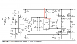
I built the lme49830 with bias IC LT1166 but it doesn't work very well.
The quiescence current at about +/-30V is 10mA.
The first issue was a oscillation at the gates of the fets. I changed C6 from 100n to 180n and the oscillation was gone.
Sine wave looks fine at the oscilloscope, but if I connect a speaker and a music source the sound is very distorted. It sounds terrible, like if the bias voltage is not high enough.
So I measured the gate voltages, the irfp240 gate voltage is about +1.7V and the IRFP9240 gate voltage was -0.7V. Is it ok?? I think not… ?!
So the next step was chancing C4 and C5 from 10pF to 27pF but nothing happened. It still sounds distorted…
Maybe it's because the red marked current source? Do I have to connect PIN1 of the LT1166 to V+ rail? I think my LME49830 will fire up if I connect Bias + with V+. So what does I1 mean?
I hope you can help me") Thanks in advance!
Thanks in advance!
Bernhard
I built the lme49830 with bias IC LT1166 but it doesn't work very well.
The quiescence current at about +/-30V is 10mA.
The first issue was a oscillation at the gates of the fets. I changed C6 from 100n to 180n and the oscillation was gone.
Sine wave looks fine at the oscilloscope, but if I connect a speaker and a music source the sound is very distorted. It sounds terrible, like if the bias voltage is not high enough.
So I measured the gate voltages, the irfp240 gate voltage is about +1.7V and the IRFP9240 gate voltage was -0.7V. Is it ok?? I think not… ?!
So the next step was chancing C4 and C5 from 10pF to 27pF but nothing happened. It still sounds distorted…
Maybe it's because the red marked current source? Do I have to connect PIN1 of the LT1166 to V+ rail? I think my LME49830 will fire up if I connect Bias + with V+. So what does I1 mean?
I hope you can help me
Thanks in advance!Bernhard
Attachments
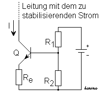
You have the CCS labels back to front.
The resistor R1 is the constant current sink.
I is fed from a +ve supply via a limiting resistor.
Re is set to zero ohms.
Now you need to turn the whole thing upside down to create a current source and use a PNP for the inverted voltage.
The resistor R1 is the constant current sink.
I is fed from a +ve supply via a limiting resistor.
Re is set to zero ohms.
Now you need to turn the whole thing upside down to create a current source and use a PNP for the inverted voltage.
I simply added a current source with a lm317 and it worked... not perfect but much better than before.
I figured out that this circuit is very, very sensible to the current source. So if it isn't exacly 10mA it doesn't work. So now I know what the problem is and can fix it.
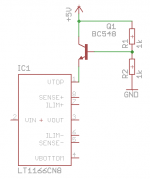
@Andrew: why do I have to build the current source upside down? I added a circuit for the current source, can I do it this way?
Thanks.
I figured out that this circuit is very, very sensible to the current source. So if it isn't exacly 10mA it doesn't work. So now I know what the problem is and can fix it.
@Andrew: why do I have to build the current source upside down? I added a circuit for the current source, can I do it this way?
Thanks.
Attachments
Hi mantabernd
I1 is used because Vtop (and Vbottom) pin, need a supply current to work right according de data sheet. Max value 75mA, common values between 15mA to 50mA. Current capability of BIAS pin of the LME49830 pin is below 3mA (according to data sheet) so a current source is needed to supply this current in order to the LT1166 works fine.
Probably your amplifier doesn't sound at the best quality because there is a current difference between N-channel and P-channel MOSFETs, since they are not totally symmetrical. Increase a little bit the value of the source resistors of the P-channel MOSFETs until both currents are the same.
Now I'm designing, simulating and building this amplifier, I would like to know how your amplifier sounds and if you did any improvement, I really appreciate that.
Best regards!
Linear provides an excellent data sheet and application note on their website -- with a schematic for the current source(s)
LT1166 - Power Output Stage Automatic Bias System - Linear Technology
LT1166 - Power Output Stage Automatic Bias System - Linear Technology
AutoNias
Links not working or is it just some problem at my end? The whole website seems to be down at the time of this writing.
Links not working or is it just some problem at my end? The whole website seems to be down at the time of this writing.
the first link takes me to
Auto Bias
the second link takes me to
http://www.data-odyssey.nl/AutoBias_II.html
Auto Bias
the second link takes me to
http://www.data-odyssey.nl/AutoBias_II.html
Sir please sorry me because i am coming with very stupid question.
I am building lme49830 based amplifier with output device 2sk1058 and 2sj162.
In datasheet of both devices it is clear that both have pinout from left to right are gate souce and drain. Mosfet k1058 drain connected to +vcc and souce connected to dmm pin to measure quiescent current another mosfet sj162 source connected to dmm another pin and third last mosfet pin connected to -vee.
Now problem is when both gate disconnected sj162 heated abruptly with smoke. My design based on amp48 schematic and suppy voltage is too low for testing purpose 25-0-25 thnx in advance for suggesting me if i have done something wrong with devices
Duplicate post from Rakesh
Sorry sir but i want immediate reply so i copy it
- Status
- This old topic is closed. If you want to reopen this topic, contact a moderator using the "Report Post" button.
- Home
- Amplifiers
- Chip Amps
- Problem with Bob Cordell's LME49830 and LT1166