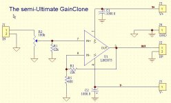
I am now starting to build a dual LM1875 amplifier, and want to keep it simple so the circuitry fits on a small board. Is the resistor and cap connecting from pin 2 to gnd neccesary? I can't see what purpose it serves, but I am sure somebody can point out its job. Also, is the 22k resistor on the input nessecary? I assume this has something to do with volume, and since I will be adding a volume control, do I need it?
Attachments
soundNERD said:I am now starting to build a dual LM1875 amplifier, and want to keep it simple so the circuitry fits on a small board. Is the resistor and cap connecting from pin 2 to gnd neccesary? I can't see what purpose it serves, but I am sure somebody can point out its job. Also, is the 22k resistor on the input nessecary? I assume this has something to do with volume, and since I will be adding a volume control, do I need it?
http://www.diyaudio.com/forums/showthread.php?postid=259496#post259496
This is the simplest you can do for NIGC. Just use the apropriate pins for LM1875. Check the sch above for even one resistor less, but I'd put the resistor to sleep well at nigt.
Greg
Attachments
the resistor and cap connecting from pin 2 to gnd neccesary? I can't see what purpose it serves, but I am sure
You should make the effort to learn some basic opamp theory. The resistor is there to set the gain of x21; without it you get unity AC gain. The cap sets the gain to unity for DC. If you replace it with a short you'll get slightly worse offset and considerably better sound.
Well I built one channel last night and am going to build the other today. I used an old split power supply that I built using a 26.6VCT transformer @ max of 1A, so through the rectifier it puts out about +-22. The rectifier also reduces current, so I am probably getting about 3/4A, right? So, I think that could and most likely is the cause for distortion. I am running an 8-ohm speaker with a portable CD player as the input. Of course the CD player could be the problem, but I think it is the low power input. It does go consiterably loud before distortion for how little power it is getting. I also noticed a large problem I am having. When there is nothing connected to the input, the speaker starts to buzz and sort of vibrate since the speaker in it is moving in and out rapidly. I really need to make it so there is no noise even with the input connected.
Also, analog_sa, what do you mean by worst offset? And by considerably better sound, do you mean crisper, less distortion, or something else?
Is it OK that I am using a 33k resistor for the feedback? That wouldn't be setting the gain too high, right? If so, I would have to use a 15k.
What is the purpose of the 1ohm resistor and the capacitor on the output? I didn't have the cap so at first I just used the resistor. The sound was not too good. So I decided to put a 0.5uf NP capacitor in place of the 0.22uf, and the sound became much better. What do these parts do?
Thanks for all of your help, Mike
soundNERD said:Well I built one channel last night and am going to build the other today. I used an old split power supply that I built using a 26.6VCT transformer @ max of 1A, so through the rectifier it puts out about +-22. The rectifier also reduces current, so I am probably getting about 3/4A, right? So, I think that could and most likely is the cause for distortion. I am running an 8-ohm speaker with a portable CD player as the input. Of course the CD player could be the problem, but I think it is the low power input. It does go consiterably loud before distortion for how little power it is getting. I also noticed a large problem I am having. When there is nothing connected to the input, the speaker starts to buzz and sort of vibrate since the speaker in it is moving in and out rapidly. I really need to make it so there is no noise even with the input connected.
Also, analog_sa, what do you mean by worst offset? And by considerably better sound, do you mean crisper, less distortion, or something else?
Is it OK that I am using a 33k resistor for the feedback? That wouldn't be setting the gain too high, right? If so, I would have to use a 15k.
What is the purpose of the 1ohm resistor and the capacitor on the output? I didn't have the cap so at first I just used the resistor. The sound was not too good. So I decided to put a 0.5uf NP capacitor in place of the 0.22uf, and the sound became much better. What do these parts do?
Thanks for all of your help, Mike
follow analog_sa' s advice and read read a couple paragraphs about how op-amps work. a 33K resistor sets the gain too high.
the RC network rolls off the highs -- it depends on the cables you are using, length of cables, type of crossover etc. whether it is necessary -- the chip amps easily go into oscillation.
i think i have posted the link to the ChipAmp calculator on Nat Semi's website 3X so I am not going to post it again.
i'm running a bare-mnimum lm1875 amp right now, 4 channels, 10 watts a channel. being my first amp, i can't compare it to anything. especailly with my current speaker problems and all.
my setup is outright terrible for DC offset. i have a difference amp for my input to a crossover (and no, that circuit isn't at all balenced desite everyone saying so). this passes DC. the chips are just 2 resistor non-inverting gainclones. gain of about 20. no zobel, no case, i do have 100nF bypass caps. power supply uses 4700uF per side. it works. i get turn on and turn off
my setup is outright terrible for DC offset. i have a difference amp for my input to a crossover (and no, that circuit isn't at all balenced desite everyone saying so). this passes DC. the chips are just 2 resistor non-inverting gainclones. gain of about 20. no zobel, no case, i do have 100nF bypass caps. power supply uses 4700uF per side. it works. i get turn on and turn off
Well, I built the second amp, and connected the thing to my PS. The first amp worked fine, but the second worked at low volumes until when I turned the volume up it would make a loud static sound out of its speaker, and affect the sound slightly out of the other speaker. When I built it, I used just a IC board from RadioShack, and mounted the chips on the same heatsink. I used wires wrapped around the leads and then soldered to them, to connect to the board. I know that the metal tab is connected to -, so I only connected - power to the - pin on the first chip, and figured the second would get it off of the heatsink. Could there be a resistance on the connection and to fix the static do I need to just connect the - pin to the - supply?
Also, about my power supply. I know that the transformer can put out 26.6VCT @ 1A according to the label on the secondary. When ran through the rectifier, a 4A one, the output voltage is +-22V, according to my DMM. I then connect the test lead to the 10ADC and turned the power supply on. The wire sparked and the DMM measured 8A between the + and -, and then I tried the + and gnd. There the screen went blank, showing an amperage over 10A. If it really were 10A, then the rectifier would be blown and going over 10A on my DMM ruins it, but it didn't. So I tried with a 0-20A DC analog meter. I got 8A between the + and - and 12A between the + and gnd. Is this possible? Especially for a 1A transformer?
Also, about my power supply. I know that the transformer can put out 26.6VCT @ 1A according to the label on the secondary. When ran through the rectifier, a 4A one, the output voltage is +-22V, according to my DMM. I then connect the test lead to the 10ADC and turned the power supply on. The wire sparked and the DMM measured 8A between the + and -, and then I tried the + and gnd. There the screen went blank, showing an amperage over 10A. If it really were 10A, then the rectifier would be blown and going over 10A on my DMM ruins it, but it didn't. So I tried with a 0-20A DC analog meter. I got 8A between the + and - and 12A between the + and gnd. Is this possible? Especially for a 1A transformer?
yeah, probably like fuses -- won't blow instantly, but given some time you are asking for it.
but the real problem is your lack of experience with the DMM. don't worry, everyones done this at least once, and it's why all the DMMs in our labs no longer measure current!
voltage is measured in parallel, by placeing a lead on one pin and the other lead on another pin. amperage is not. you must connect the metere in series, you would disconnect the wire attaching to +v on the transformer, thne attach the DMM to +V and that wire.
when you measure current, the meter is a short circuit, which allows current to pass.
like i said, everyone has done it at least once.
- Status
- This old topic is closed. If you want to reopen this topic, contact a moderator using the "Report Post" button.
- Home
- Amplifiers
- Chip Amps
- Are these parts needed for the LM1875?