Hello,
I am new here in this forum. I have some experience in the audio world in general.But this is my first time setting up a DIY amplifier.
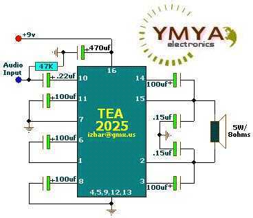
First off I have some TEA2025 chips lying around, 3 of them to be exact. So for my first try, I followed this diagram on a breadboard.
I think I have everything down correctly and powered by a 9v dc adapter/transformer, followed the polarities but I have a few questions.
-first is, I am confused which is the positive output for the speaker leads , is it the <2,3> output or the <14,15>
-second once I plug it all in, except for the input signal, I get a constant popping sound and when I introduce the input signal I get very little music and it all sounds VERY distorted.
-last is any suggestions as to how I can configure this to be a subwoofer amp?This was intended for the subwoofer of a 2.1 speaker system
any help would be appreciated, I have a little electronics background..
Thanks in advance
I am new here in this forum. I have some experience in the audio world in general.But this is my first time setting up a DIY amplifier.
First off I have some TEA2025 chips lying around, 3 of them to be exact. So for my first try, I followed this diagram on a breadboard.
I think I have everything down correctly and powered by a 9v dc adapter/transformer, followed the polarities but I have a few questions.
-first is, I am confused which is the positive output for the speaker leads , is it the <2,3> output or the <14,15>
-second once I plug it all in, except for the input signal, I get a constant popping sound and when I introduce the input signal I get very little music and it all sounds VERY distorted.
-last is any suggestions as to how I can configure this to be a subwoofer amp?This was intended for the subwoofer of a 2.1 speaker system
any help would be appreciated, I have a little electronics background..
Thanks in advance
Pin 15 is the output for pin 10 input.
Looks like grounding issue. You run a long supply cable from a not so good adaptor. Best is the diode bridges are on PCB near the chip.
Is 5W enough for a subwoofer? You need an active crossover. One opamp IC is enough but that may be too complicated, no?
Looks like grounding issue. You run a long supply cable from a not so good adaptor. Best is the diode bridges are on PCB near the chip.
Is 5W enough for a subwoofer? You need an active crossover. One opamp IC is enough but that may be too complicated, no?
Neither pair. The output is an AC signal and so it doesn't have a specific positive polarity.-first is, I am confused which is the positive output for the speaker leads , is it the <2,3> output or the <14,15>
Another way it can be viewed, though, is that the signal input is to the noninverting input pin 10 (IN 1+) of the amp. That means that pin 15 (OUT 1) goes positive when the signal input goes positive. That's a good reason to make pin 15 the bridged positive speaker connection. Pin 15 is also the positive (ie ungrounded) speaker connection in stereo mode.
That could be a symptom of time constant capacitor discharge. You stated, "I think I have everything down correctly and powered" and you should inspect your work until there are no uncertainties. I'm aware that that doesn't sound like help, but it really is. Check the amp circuit and the power supply.-second once I plug it all in, except for the input signal, I get a constant popping sound and when I introduce the input signal I get very little music and it all sounds VERY distorted.
The circuit shown is nearly identical to the example circuit in the datasheet. One thing that application doesn't show is a small value (eg 0.1µF) bypass capacitor on the V+ supply. It will help stabilize your circuit. Further details are in the datasheet. Have a copy handy while you build your amp; it will be useful.
You'll want an active filter that sums the left and right channels and processes it through a low pass filter. This reduced bandwidth signal is then fed to the amp input.-last is any suggestions as to how I can configure this to be a subwoofer amp?This was intended for the subwoofer of a 2.1 speaker system
Thank you very much for the input, I am learning a lot as it is =), I removed the 0.22uf cap from the 10 input and the popping disappeared. I double checked the way things were wired in place. What am I doing wrong? =)
"You'll want an active filter that sums the left and right channels and processes it through a low pass filter. This reduced bandwidth signal is then fed to the amp input." this is an interesting idea...let me look this up somewhere.. Do I need to upload pics of my project on the breadboard? will this help?
"You'll want an active filter that sums the left and right channels and processes it through a low pass filter. This reduced bandwidth signal is then fed to the amp input." this is an interesting idea...let me look this up somewhere.. Do I need to upload pics of my project on the breadboard? will this help?
That's seems an easy fix for the popping problem. That capacitor blocks DC from the input, so if there is no DC on the input anyway (for instance, your source has DC blocking at its output) it isn't necessary. But you'll want to check that there is indeed no DC at pin 10.
You can find the filter online as a subwoofer circuit, or separately as a mixer circuit and a low-pass filter circuit, which are then just put together to make the whole. Neither should be difficult to find. Pics aren't necessary at this time. When it comes to making a permanent board, you may want to upload your layout then.
You can find the filter online as a subwoofer circuit, or separately as a mixer circuit and a low-pass filter circuit, which are then just put together to make the whole. Neither should be difficult to find. Pics aren't necessary at this time. When it comes to making a permanent board, you may want to upload your layout then.
The Dc adaptor that you are using is not filtered enough, you are getting too much ripple coming from the adaptor and it is induced in the circuit.
add something like a 4700 uf at 16 volts and that should take care of the ripple.
The amplifier is actually a stereo amplifier but is configured as a bridging amplifier, half of the amp is working in an inverting mode and the other halh is working in the non inverting mode, thus thus there is no positive and negative on the output.
http://www.st.com/internet/com/TECHNICAL_RESOURCES/TECHNICAL_LITERATURE/DATASHEET/CD00000172.pdf
thus there is no positive and negative on the output.
Just don't forget to wire the speaker similarly between left and right. If you can, wire positive speaker to the pin 15. Or simply listen to choose which one is better, if you have golden ears

- Status
- This old topic is closed. If you want to reopen this topic, contact a moderator using the "Report Post" button.
- Home
- Amplifiers
- Chip Amps
- newbie here asking for help