Recently I build LM1876 sounding good. Mute not used. I think I am near to simple solution.
If I supply below +2.5VDC at mute pins. Amp in play-mode. And supply > 2.5VDC Amp in Mute-mode. (Please correct me if I wrong)
Yesterday, I test voltage divider.
Test 1 : (Figure A ) 20VDC Supplies output is 10VDC (Approx)
Test 2 : (Figure A ) Adding 2200uf Capacitor, I test with Digital Multi Meter (DMM) I hold DMM's pins at output & ground and told my son to turn power ON, I found, DMM shows 20VDC and dropping slowly and settled to 10VDC approx.
I want my circuit should draw 20VDC when I power ON and should drop slowly and settle to below 2.5VDC (which is mute pins requirement for play-mode)
One solution : If I raise R1=22k the output voltage should dropped.
Or Another solution : (Figure C) My supply voltage is 5VDC then output must be 2.5VDC
Summary : (Figure C) Input 5VDC output 2.5VDC with capacitor delay.
I have already build complete Amp which is sounding good. But I did not attach this circuit to mute pins. I fear, I don't what to spoil my amp. I am not electronics man so can you advice me, this (voltage divider) circuit would work for me ? Or Should try this circuit with mute pins ? just for try without damage.
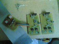
Attachments
Assuming you use a symetrical supply.
As per datasheet, the mute pin doesn't want to see more than 5 volts.
Only fig 3 is acceptable.(10v output must be a mistake?)
Making R1=R2 stabilise at 2.5v which is too near from muting treshold. Better to go lower using R1 larger than R2.
You can use a smaller cap if using a larger R2 value. IT's the time constant R*C that counts.(the time it takes for unmuting)
@ bobodioulasso : Thank you for boosting my confidence.. Audio-Electronics is my hobby. I get few time to do this. Today I am going to try this.
@Minion : LM1876's mute pin works like if V+>2.5V, amp is silent, V+<2.5V Amp is play mode. When I power switch ON, I need V+ should be >2.5V and should drop slowly and stabilize below 2.5V. (which is too near from muting treshold.) And I think 2.5v zenner, would supply constant 2.5V ( please correct me if I am wrong )
Or, Please post in detail what you have to advice ?
Just hook up a time-constant to (without dividing action) the MUTE pin, with a 100k protection resistor in series, see datasheet Fig.7 for the basic idea. The time-constant is a C from Vcc and and R from Vss (NOT GND!) so that initially after power-up, while the C is charging the MUTE pin is being pulled up putting the chip into MUTE state. You won't need more than a second of delay, so something like 220uF+47k should do.
Figure C must have an AC input for the voltage doubler action to happen.Recently I build LM1876 sounding good. Mute not used. I think I am near to simple solution.
If I supply below +2.5VDC at mute pins. Amp in play-mode. And supply > 2.5VDC Amp in Mute-mode. (Please correct me if I wrong)
Yesterday, I test voltage divider.
Test 1 : (Figure A ) 20VDC Supplies output is 10VDC (Approx)
Test 2 : (Figure A ) Adding 2200uf Capacitor, I test with Digital Multi Meter (DMM) I hold DMM's pins at output & ground and told my son to turn power ON, I found, DMM shows 20VDC and dropping slowly and settled to 10VDC approx.
I want my circuit should draw 20VDC when I power ON and should drop slowly and settle to below 2.5VDC (which is mute pins requirement for play-mode)
One solution : If I raise R1=22k the output voltage should dropped.
Or Another solution : (Figure C) My supply voltage is 5VDC then output must be 2.5VDC
Summary : (Figure C) Input 5VDC output 2.5VDC with capacitor delay.
I have already build complete Amp which is sounding good. But I did not attach this circuit to mute pins. I fear, I don't what to spoil my amp. I am not electronics man so can you advice me, this (voltage divider) circuit would work for me ? Or Should try this circuit with mute pins ? just for try without damage.
You cannot get that doubled output voltage from figC if the input really is 5Vdc.
Today's Job, SUCCESS
As per fig.D, Regulated supply 5V supplied. After various values of resister, finally selected R1=100K and R2=2.7K. Mute is working. 2200uf cap delaying good time. Several times Power ON and OFF. I found NO pop or click at power on.
I kept circuit as it is for half an hour. And power on again. This time amp was mute and could not play. Power switch OFF and ON immediately, Amp started playing after 2-3 Seconds. I could not understand, why amp could not played first time ?
One more thing, this circuit could not work on power OFF. There is little POP/CLICK on power OFF. I think some expert's experiment needs here.
I am not going to surrender and accept as it is. Some experiment will do in next day..
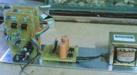
Attachments
I have no explanation at this time for the half-hour problem. For the power OFF problem... on power-up, the mute needs to start high and switch low. This has obvious inherent drawbacks. At power OFF it has to quickly switch high again, and again there are the same inherent drawbacks.
An inverter, discrete or integrated, may provide a solution, but I agree experimentation is necessary.
An inverter, discrete or integrated, may provide a solution, but I agree experimentation is necessary.
the 2200uF cap is discharged before first start up.
That applies 5V to the mute pin when you start up from cold.
Then the resistors take over and slowly charges the 2200uF to final voltage. This reduces the mute pin voltage to ~2k7/100k*5V. This charging follows the usual RC time constant law. ~ 95% charged in 60ms.
Will the mute pin survive that 5V pulse? and after the onehundredandtwentythird time?
Is this another unhelpful post?
Still there is hope
There is no problem in mute circuit... Overall something is wrong with my Amp or power supply. I disconnected mute and played as it was basic build. I found, 1st time it does not played. Switch off and immediately switch on and played. Just playing half an hour, then switch OFF and immediately switch on not played again..
It is working like toggle switch NOT PLAYED = SWITCH OFF- AND SWITCH ON = PLAYED..
why ? I found, SWITCH-ON = NOT PLAYED. condition .... I measure the voltage at power supply. 22(+/-)VDC correctly supplied to Power-amp but Regulator 7818 is not supplying +18VDC DMM shows below <1 vdc WHY ? I could not understand.
Again SWITCH-OFF AND SWITCH-ON condition Amp stared playing and Regulator 7818 correctly shows +18VDC by DMM.
I have fitted 7805 regulator for muting. 7818,7918 for crossover.
I kept circuit as it is for half an hour. And power on again. This time amp was mute and could not play. Power switch OFF and ON immediately, Amp started playing after 2-3 Seconds. I could not understand, why amp could not played first time ?
There is no problem in mute circuit... Overall something is wrong with my Amp or power supply. I disconnected mute and played as it was basic build. I found, 1st time it does not played. Switch off and immediately switch on and played. Just playing half an hour, then switch OFF and immediately switch on not played again..
It is working like toggle switch NOT PLAYED = SWITCH OFF- AND SWITCH ON = PLAYED..
why ? I found, SWITCH-ON = NOT PLAYED. condition .... I measure the voltage at power supply. 22(+/-)VDC correctly supplied to Power-amp but Regulator 7818 is not supplying +18VDC DMM shows below <1 vdc WHY ? I could not understand.
Again SWITCH-OFF AND SWITCH-ON condition Amp stared playing and Regulator 7818 correctly shows +18VDC by DMM.
I have fitted 7805 regulator for muting. 7818,7918 for crossover.
Attachments
Schematic?
@bobodioulasso, sorry for late. Infact I did not have schematic and I build it. Mean time I found when I connect my mp3 player DAC then only it behave like this (post # 12)
I suspect my power supply Please comment..
I think you cannot power up simultaneously the crossover and the ampOpps. This is schematic
A crossover produces a big thump at powering on and off, so it's preferable to power both on and off in the right sequence.
I am not shure you can manage this using mute only.
Mute pin needs series resistor to limit current.
- Status
- This old topic is closed. If you want to reopen this topic, contact a moderator using the "Report Post" button.
- Home
- Amplifiers
- Chip Amps
- LM1876 Mute by Voltage divider.