So, how big are the woofers on these front speakers?
Do you intend full audio band or a bit less bass?
just small sony xplode car speakers,,possibly around 5''/6" even im planning to update my druvers.I need mid and tweeter,,I have another amp for woofer.
Hi,
Daniel, great project. I have been wanting to do a point to point amp for a while, and this really intrigues me. So in doing some initial planning I have my first question. In refering to your original schematic, are all of the resistors 1/4 watt? In another post you mentioned that you were using a 1/2 watt for your feedback resistor, but you thought the sound quality degraded with higher wattage value. What composition do you recommend for the resistors? Would you recommend somthing like a riken for a feedback resistor (or somthing from mouser as I have already submitted an order to partsconnexion today)?
Sorry, that is more than one question. Thanks
Thanks.Hi,
Daniel, great project. I have been wanting to do a point to point amp for a while, and this really intrigues me. So in doing some initial planning I have my first question. In refering to your original schematic, are all of the resistors 1/4 watt?
They are all 1/4w.
Output RC can be used with a 1/4w 10R and 10n capacitor--That's pretty minimal but usefully retards RF and can't shunt any audio.
That's seems backwards, for (bad) example: An 1/8w feedback resistor will degrade audio because there's a Power Amp pushing at it--Higher current into smaller wattage resistor is bad for quality.In another post you mentioned that you were using a 1/2 watt for your feedback resistor, but you thought the sound quality degraded with higher wattage value.
In a different way, 1/2w, 1w, 3w, might be bad for feedback resistor due to their larger size = higher inductance, and higher inductance puts MOAR gain on HF, which we don't want to do.
Ordinary 1/4w feedback resistor is unlikely to degrade the audio when there is low current. But, there may be room for improvement.
Parallel 1/4w resistor for feedback, as shown in the photos is great because it withstands higher current without degrading audio and because it cuts inductance in half. It also allows convenient values, such as 60k and 75k. . . of really really non-inductive resistors. I fluxed the leads before soldering, so that connections will be solidly operating as 1 piece for good quality.
Xicon and Koa 1/4w Carbon Film are suitable. Radio Shack apparently carries Xicon. Mouser has both. The leads on these products are nice and thick, and that's desirable. Approximately, 12 cents for a paralleled pair of good quality carbon film will have less inductance than a single expensive carbon comp.
P.S.
Entertaining spot for 1/2w carbon film is the feedback-shunt resistor (2.7K on the schematic). Xicon and Koa are suitable. Now, the entire voltage divider has 1/2w capacity.
P.P.S.
When the lower inductance feedback resistor (parallel quarter-watt resistors) is set against the higher inductance feedback-shunt (solo half watt resistor) in a voltage divider, then gain is decreased for HF. This is apparently what people are trying to accomplish with expensive boutique resistors except that I've done it for pennies and on purpose. The effect is miniscule and you can notice it only because there's gain on it.
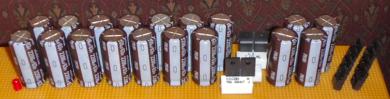
Daniel,,I don't have 1.3 R,3W but I have 1.5R,1W only,I don't hav 6A05 ,,but I have 6A04 diodes.Any alternatives ?Here are the 2200u caps:
how about carlos psu.
Attachments
6 parallel 1.5R = 0.25R, 6W and ok. 6A04 is fine.Daniel, I don't have 1.3R 3W but I have 1.5R 1W only; I don't have 6A05 but I have 6A04 diodes.
You may want to find higher current resistors; however, the good news is that 6A04 assists in managing the surge current.
Last edited:
It is true that we should not. Please avoid extra bypass for now.thank you so much for your quick reply.
Should we not put a 100nf in the psu board ?
Later, and only based on merit, you can try any of the following:
Electrolytic of 2.2u or smaller.
Polyester of 33n or smaller.
Polypro/ceramic of 4n7 or smaller.
You can see if any of those help audio, later, after the amp is up and running. Omit for now.
Yes, for 1w drainer resistors.Can I use 2.2K instead of 2.7k,
However, for 1/4w drainer resistors, you can use 4 of 10k in parallel to make a 1w 2.5k resistor.
Drainer resistor value adjusts time to drain. Adapt to suit.
These indicators are very important for safety and also error detection.is the color of LED specific ?thank you.
The LED Forward Voltage Drop figure is important and we want 2v or less (preferably less than 2v) so:
Clear body led (with the top filed flat for wide angle viewable) Red, Yellow or Amber. And, Red is best, 1.6v, yellow okay, 1.7v, and amber works, 1.9v.
Colored body led of green orange or red, is internally a yellow led and colored body led are useful because so easily wide angle viewable.
LED Resistor Calculator
Please don't run more than 8ma on a 20ma led.
Observe resistor wattage tolerances too.
I'd like both rails identical for voltage, so if you want different colors, used the colored body LED (they're yellow led inside).
You can make a good head start easily with a 1u electrolytic. Otherwise, I'd use polyester.what types of capacitor you use for input cap,,i,e .68uf? tantalum, polyester, propylene? or just electrolyte?
one silly Question,how does led help in safety,,error detection ?LED
These indicators are very important for safety and also error detection
Mainly, the feature is to keep fingers away from lethal charge.
Compare:
♦ Without LED's, handling a power supply to use a multimeter for finding out how much charge is a lethally faulty idea because lethal charge may be present at time of handling, and that's horrible.
♦ However, waiting for the LED lights to turn off indicates that the remaining charge is probably not lethal.
See the difference?
Those LED's might save your life.
With the LED's, some error detection is also done at power up/down time.
If one LED goes either on or off before the other, that indicates an amplifier problem or hookup problem. The very first time I added LED's to a power board, it indicated that one of the screw connections was slightly loose. This condition was detected easily and immediately.
Because of the features of safety enhancement and fault detection, I have added LED's to ALL of my power supplies.
Last edited:
Thank you so much Daniel.Actually I have started constructing the psu like you have,I have only 12x2200uf,50V.The shop has got 4700uf,50v,3300uf,50v good quality caps.Can I use 3300 or 4700 ,50 v with 12x2200uf caps ?Anyway the design,the stuff is so awesone,,heavy in a sense,,I just kept starring at it.
It would be wrong to throw a 3300u or 4700u in amongst that group of 2200u; however, you can put the 3300u OR 4700u before the resistor--The odd value caps can go directly at the bridge rectifier.Thank you so much, Daniel. Actually I have started constructing the psu like you have. I have only 12x2200uf, 50V. The shop has got 4700uf, 50v; 3300uf, 50v good quality caps. Can I use 3300 or 4700, 50v with 12x2200uf caps? Anyway the design,the stuff is so awesome, heavy in a sense; I just kept starring at it.
Example (one rail described below--other rail is copy of same):
Rectifier, 3300u, Resistor||Diode, 2200u, 2200u, 2200u, 2200u, 2200u, 2200u, cable, amplifier
Notice that it is the Series Element (Resistor or Cable or Transistor or Inductor or Regulator or Diode or PCB Trace are series elements) that allows us to connect a different size capacitor. The series element (such as a Resistor) creates a "Ballast" that helps Prevent problems in the power circuit.
Rules of thumb:
Don't put more than 7 caps directly in parallel
Don't directly parallel different size capacitors
Here's a larger size power supply built to this spec.
I made it for the TDA7293-Parallel amp, and that power supply is just barely big enough to attempt powering one Honey Badger Monobloc. If there's anything beastly about this little power supply, that is aggressive charge speed for high resolution bass support.
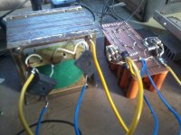
Does this occur when loaded or only when unloaded?simply14prem said:I called it a BEAST, I have never design a psu like that. There is a slight problem--There is a very small voltage imbalance in two of the secondary (dual secondary), Any method to level them, or should I rewind the transformer?
Are the bridge rectifiers exactly the same model for both secondaries?
You can try snubbing the transformer secondaries (2u polyester + 50R variable resistor makes adjustable RC's) to remove noise. Try it first on your "too high" side.
Can you post a photograph?
Fairchild Stealth are suitable, well behaved in linear supplies and extremely fast, but 8 of them are more difficult to install than a pair of KBPC1004's.simply14prem said:Do you know any fast acting bridge diodes?
Xformer have been rewinded as it is EI, so I love winding it in bifiller.It's cool now except the spark when power goes off.
Now I will play with the amp.
1.I will try 680+120=800,for the FB shunt R.
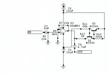
2.Put a buffer from NE5534, with or without the Class A biased transistor.
I think my amp is still muddy.I need to tweak it.
Also Daniel, I can't find any 2u to use from rail to rail, so sad.
Plz check these buffers ,,actually i like the one posted.Plz recommend me a good buffer.
Building a buffered Gainclone chip amp.
Now I will play with the amp.
1.I will try 680+120=800,for the FB shunt R.
2.Put a buffer from NE5534, with or without the Class A biased transistor.
I think my amp is still muddy.I need to tweak it.
Also Daniel, I can't find any 2u to use from rail to rail, so sad.
Plz check these buffers ,,actually i like the one posted.Plz recommend me a good buffer.
Building a buffered Gainclone chip amp.
Attachments
Last edited:
Sparks? That's construction error. The connections are a bit flimsy and voids are causing sparks, so you need MUCH THICKER traces (probably needs reinforced with wire and solid soldering).
Also, the pi filter resistors need to be paralleled with minimum pin length and not look like a fishing net.
I think I see a ground loop that might cause dulling, so that needs fixed. Hey, I've made a drawing for you.
The green traces have the conductor Thickest to Farthest caps.
Also, the pi filter resistors need to be paralleled with minimum pin length and not look like a fishing net.
I think I see a ground loop that might cause dulling, so that needs fixed. Hey, I've made a drawing for you.
The green traces have the conductor Thickest to Farthest caps.
Attachments
- Home
- Amplifiers
- Chip Amps
- Point 2 Point (no PCB) for TDA7293, TDA7294, TDA7295, TDA7296.