lower cost
Stereo amplifier chip $7. No costly lethal transformers to buy or touch.
TDA1554Q Manu Philips Encapsulation Zip 2 x 22 W
The TDA155Q amplifier has a smooth treble that's not raspy, and therefore I'd propose that it would match up with the remote control head units at post 12.
The efficiency is very high for a class B, so heatsink expense is minimal--could use a plastic project box, drill holes in the bottom of the box, cut most of the top out of the box, and bolt the typically included metal plate atop the box, forming a convection cooler, in which case the chip mounted on the metal plate would hang down inside the box. Air goes in at the bottom (if you add rubber feet) up to the chip and then hot air is expelled at the small gap that is all the way around the top edge.
It would look like a black box with an aluminum top.
Or it could be done in color (optional):
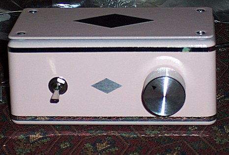
My own amp is black, silver and 1/3rd larger.")
Enclosure expense is minimal for cool running amp with external power supply.
It looked better and ran much cooler after I added the square rubber feet (1 cm square by 2/3rds cm tall, feet to make the air vents work).
The amplifier is built with:
Inexpensive 15v cord from post 17
2200u 25v cap
100u 25v cap
22u 25v cap
100n cap
2 of 330n cap (wima polyester or nichicon electrolytic)
2 of 10k resistor for input loads
10k resistor for mute (un-mute)
Plastic project box (with flat metal shelf included)
Can use remote control head-unit from post 12 instead of the mechanical volume control.
TDA1554Q amplifier is extremely easy, inexpensive and durable, but does not naturally have either a laid back or euphonic sound. However it is possible to add those features via simple external circuits.
Optional "open sound" effect:
1). BlareBuster circuit at input with 1 20k pot, 2 of 47u cap and 2 of 100n or 1uF ecaps.
2). Power filter made with 1 fast silicon diode, a 1 ohm resistor and a 22u or larger cap.
Stereo amplifier chip $7. No costly lethal transformers to buy or touch.
TDA1554Q Manu Philips Encapsulation Zip 2 x 22 W
The TDA155Q amplifier has a smooth treble that's not raspy, and therefore I'd propose that it would match up with the remote control head units at post 12.
The efficiency is very high for a class B, so heatsink expense is minimal--could use a plastic project box, drill holes in the bottom of the box, cut most of the top out of the box, and bolt the typically included metal plate atop the box, forming a convection cooler, in which case the chip mounted on the metal plate would hang down inside the box. Air goes in at the bottom (if you add rubber feet) up to the chip and then hot air is expelled at the small gap that is all the way around the top edge.
It would look like a black box with an aluminum top.
Or it could be done in color (optional):
My own amp is black, silver and 1/3rd larger.
Enclosure expense is minimal for cool running amp with external power supply.
It looked better and ran much cooler after I added the square rubber feet (1 cm square by 2/3rds cm tall, feet to make the air vents work).
The amplifier is built with:
Inexpensive 15v cord from post 17
2200u 25v cap
100u 25v cap
22u 25v cap
100n cap
2 of 330n cap (wima polyester or nichicon electrolytic)
2 of 10k resistor for input loads
10k resistor for mute (un-mute)
Plastic project box (with flat metal shelf included)
Can use remote control head-unit from post 12 instead of the mechanical volume control.
TDA1554Q amplifier is extremely easy, inexpensive and durable, but does not naturally have either a laid back or euphonic sound. However it is possible to add those features via simple external circuits.
Optional "open sound" effect:
1). BlareBuster circuit at input with 1 20k pot, 2 of 47u cap and 2 of 100n or 1uF ecaps.
2). Power filter made with 1 fast silicon diode, a 1 ohm resistor and a 22u or larger cap.
Last edited:
One thing worth saying is to buy casework and power supply plus heat-sinks is expensive . Giving it a little thought I would build these as Monoblocs ( a power supply for each channel ) . For arguments sake we could say 4 x 20 to 25 V DC (4 x 22 000 uF 35 V ) . The transformers 160 VA . This would allow to build a bridge amplifier or conventional 100 W stereo design later ( 2 x 40 to 50 V 320 VA ) . The heat-sinks 0.7 to 0.5 degrees per watt . With the heat-sinks I have listed one should be enough . The casework could be bought large enough to take one more if required . As a rule of thumb AB amps push out the power they give to the speakers as heat ( 50% realistic efficiency , not 67% theoretical ) . It is said 1/6 the stated output if undistorted music is the true average maximum ( 1/3 if Techno ) . That suggests even one of my recommended heat-sinks should work for 2 x 100 W real music if typical class AB . There are complicated ways of calculating this which I have found to be a bit unrealistic in real life . Mine is if you can not hold the heat-sink for 10 seconds it is too hot ( > 60 C ) . If you have the unit in a cupboard or the ambient temperature is high then pay attention to this . For a power amp that has generous heat-sinks one can use a wooden box , hum and noise should be OK . Some Audiophiles prefer it ( DNM ).
Some people say a good amplifier is 80 % power supply ( Naim of old ) . I suspect that is true . The point about Monobloc is the cost is not greatly more and it will make a small difference . My assumption if going to 100 W conventional is to use it as a single shared power supply ( +/- { 40 to 50 V } ) . Then one can duplicate as a Mononbloc if wanting better . 160 VA is about right for a real world design 100 W ( 320 VA both channels ) . Remember 160 VA is the safe operating point , the transformer will give a littler more on a transient with complete safety . Even Techno music should be OK . I would say even if using a switchmode PSU etcetera plan as if one day doing it the conventional way . Switchmode can make the efficiency better so might be justified . Like butter and margarine I prefer butter . In truth both have merit .
Buy Heat Sinks Heat sink,0.72deg C/W 200x125x25mm 25g AAVID THERMALLOY S586/B/125 online from RS for next day delivery.
MCTA160/18 - MULTICOMP - 160VA TOROIDAL 2X18V | CPC
ECOS1VP333EA - PANASONIC - CAPACITOR, 33000UF, 35V | CPC
I suspect only when we get to 100 Watts is it worth the trouble to build something . Comparing a Quad 405 we might buy on eBay we could be doing better to make it ourselves . I totally beleive someone taking the trouble to learn the basics can make something better than commercial designs . If I take up golf I can not imagine I would get that far as a new hobby I could make my profession . With electronics it is totally realistic to rise that far and quickly with a little help .
http://www.ebay.co.uk/itm/Quad-405-..._HomeAudioHiFi_Amplifiers&hash=item27ccbd84b9
http://www.ebay.co.uk/itm/Quad-405-..._HomeAudioHiFi_Amplifiers&hash=item27ccbd84b9
I think it is worth designing the power supply as the primary component . My idea to have either approximately +/- 25 V or +/- 50 V available .
There is a secondary reason . If the +/- 25 V is over specified the first Audiophile principle is researched . Is it worth having an over specified PSU ? Mostly it is , if only that it can be used again . I suspect it is a totally good idea . I doubt the cost difference is more than $30 above minimum requirements .
Rightly or wrongly 2 x 100 W output is considered true hi fi . Many PA people will accept it as a minimum requirement also . I suspect most amplifiers would sound as good if using all the same parts and only 20 Watts . the Yamaha class A or class B design did . It was a great amplifier both ways , the class A was better . The PSU I described with heat-sinks to match work be fine . Alas chip amps must be forgotten if so . My poor cousin Velleman kit could be converted to do that . There are better options . However being class A might be a decisive victory .
My point remains . Take the case , heat-sink and PSU very seriously . The amp can be changed many times .
If you calculate carefully the 25 V 50 V option is one of the best .
Yamaha CA-1000 on thevintageknob.org
Last edited:
..... Alas chip amps must be forgotten if so ....
Sorry, I lost your logic here. Can you explain?
Sorry all . Writing would never make make fortune . The point I was making is the power supply is a critical decision if saying money determines our reason for starting the project . Like in most things it is the critical 20 % extra that should be spent . Fascination might cause someone to go further than intended . If so my 25/50 V option should be future proof . The Yamaha Class A + AB rearranged it's power supply and biasing to have either option . As far as I know chip amps do not convert to class A ,where as the simple Velleman kit could be converted . In life most people have goals , class A is a goal of most who build amplifiers .
This is how many discover class A . Douglas Self makes it easier . Well worth a read .
http://diagramas.diagramasde.com/audio/Linsley Hood Class.pdf .
Perhaps even this amp would adapt to my power supply ( +/- 22 V is close ) .
http://diagramas.diagramasde.com/audio/Linsley Hood Class.pdf .
Perhaps even this amp would adapt to my power supply ( +/- 22 V is close ) .
To eliminate the audio effect of sticking, switching, glitching, etc. . . bias in the Class AB amp can be increased to play the 1st watt or even more in Class A. Thus the popular trick of swamping clumsy with bias is the cause of poor efficiency in linear audio. Personally, I find it most unfortunate if such inefficient practices are habitual... .Class A is a goal of most who build amplifiers .
So my goal is the opposite--I like well done high efficiency linear audio.
Thanks Nigel, That's probably a rather complex area for a thread like this, but it did prompt me to try to refresh my understanding of the classifications. Found a good page on Wikipedia (power amplifier classifications section down the page) that has layman level explanations for those who are interested.
I'll be interested in hearing more about the class A / chipamp relationship from others.
I'll be interested in hearing more about the class A / chipamp relationship from others.
Douglas Self describes a blameless amplifier . He includes a class A amplifier to be certain he offers all possibilities . He does this by converting his blameless class B to pure class A . In doing this he finds a small advantage as we should expect . One thing he does look at is maintaining negative feedback to the highest possible frequency to get blameless class B .
The Yamaha A + AB is one of my favourite amplifiers . I am not a great fan of others they have made . I have always said to myself one day I will make one . The Douglas Self example seems best . His designs are available as kits .
Daniel I 101 % agree with you . In my job I crave the 67% efficiency of a class B amps ( G , H also ) . If I get it I don't need complex solutions . I suspect a blameless amp can sound better than the class A version as it doesn't saturate the power supply . A controversial point of view and I am being deliberately that . Many know I knock Mr Self , I suspect he is >95% correct . The book is a bargain . However like appreciating art it should be your guide and not dictate your taste .
Distortion In Power Amplifiers
One can attempt class A from chip amps with a pull up or more usually down resistor to the voltage rail ( up to +ve ) . It has to pull a lot of power to do anything . If we can get to 4 W in A then maybe it is doing something ? As long as the amp is beefy enough and the resistor also it is a simple switch job to test it . Doubtless the power supply will be an issue if so . I have tried it and it is possible . Things will get very hot . Valves( tubes ) offer simple class A , my advice is learn the transistor versions first if at all . Valves require much study . Most valve kits need personalizing . Most transistor kits less so .
Returning to the nub of my argument . 18 - 0 - 18 V AC 160 VA is my universal transformer choice ( 2 for 2 x 100 W amp ) . Use as few or as many as required . 35 A bridge rectifier ( cheap , easy to fit ) . As many > 22 000 uF 35 V capacitors as required . 15 - 0 - 15 AC an alternative if looking more to the +/- 20 or 40 V DC range . If a beginner can learn this one thing the success of the amplifier is almost guaranteed . By that I mean better than commercial designs . Being ultra simplistic one can over engineer 100 % more than I suggest and perhaps still be spending wisely . 160 VA for class B 100 W is almost as small as one should dare go .
I will say something again to be deliberately controversial . I suspect most people who think about these things think of an amplifier as it's transistors and how they are arranged . I suspect most commercial amplifier designers think it is the quality of the power supply that determines the outcome ? The active circuit is the icing of the cake . Most high quality circuits I suspect on a blind listening test will be hard to identity between very good and best we can do . A low grade power supply should be obvious and will degrade the best amplifier in the world into something below an off the shelf Rotel budget amp .
Many Japaneses amplifiers in the past had circuits so absolutely blameless they must be as near perfect as we can get ? Many sounded very mediocre . They were penny pinched in the power supply department . One day I must buy one and give it what it should have had . The Yamaha I so love perhaps was forced by it's class A side to be properly equipped ? It sounded wonderful . Possible the best amplifier reference in the World ?
RaHza
I'm going back to basics on a new chip flavor with this kit. You can purchase a mono setup at the same site.The vendor is very good with customer support if you get stuck. You can of course go all the way back to making your own board or breadboard assembly (per Andrew & Daniel) for even more learning and adventure
I'm putting together the same little amp. Fired it up the other night and got some pretty clean audio on the bench. With a speaker up to my ear I could not hear any hum. Quiet as could be. Haven't finished the enclosure yet, but will upload some pics soon.
Rick
Hey, sounds like great fun. I haven't placed my order yet as I am waiting a response from the vendor. Since I'm testing other approaches I've requested some information on a Pass F5 based kit that I might purchase at the same time.
Very interested in your build pics and your impressions once everything has settled in.
Thanks, Amp Addicted in Michigan.
Very interested in your build pics and your impressions once everything has settled in.
Thanks, Amp Addicted in Michigan.
For example, not all Class 5 Efficient supplies are switchmode--some are linear. Likewise Class B amplifiers aren't limited to any prefabricated efficiency figure. I've done several in the range of 70% to 80%, and notice that Class D also does ~80% while driving 4 ohm speakers or half the output power brag while driving 8 ohm speakers (and I'm not impressed with 92% efficiency at the cost of half power). This little fact often comes as a surprise to people who assume Class D won't need a heatsink (kerblooie). When it comes to durable current Linear has switchmode beat--My linear efforts will haul out their maximum current, endlessly, without breaking, much unlike switchmode technologies that are only good for half of their brags. Ever tried a 300w computer power supply in a PC that actually needs 300w? Won't even start.. . . In my job I crave the 67% efficiency of a class B amps. . .
In my view Linear still has some life left in it, but we need interesting challenges, such as: "Contest: Class B power amp in a mint tin." sort of thing where the parameters force paying attention to efficiency of linear electronics. Without the crutch of giant heatsinks and endless space, the linear designer would then have to pay attention, since the crutch of swamping clumsy with bias would not be available.
I'm not suggesting power amp in a mint tin except as a design exercise for assuring efficiency. However, I've never used a heatsink that large for a Philips Class B car chip (11w to 8R *2 channels). Even though a mint tin is an ostentatiously large heatsink for efficient Class B, a problematic factor is heat at the capacitors.
I would love to see some creativity and design instead of cranking up bias dials.
OH! Quad Rail! Now it makes sense. That looks handy for some applications. Instead of the 2 transformers, we could substitute use 4 of double-insulated 25v SMPS (implying that earth ground is later assigned to speaker ground via ground loop breaker) But, sir, the title of this thread is Basic, and I don't think that the quad rail is basic.. . .Returning to the nub of my argument . 18 - 0 - 18 V AC 160 VA is my universal transformer choice ( 2 for 2 x 100 W amp ).. . .
This thread needs either 1 transformer or 1 SMPS.
SO, either 1 of 18,0,18vac transformer, a power board and LM1875 or
an SMPS and a car chip for less chance of a shock.
Last edited:
I recently posted the figure (78.5%), for a capacitively-coupled class-B amp at least. I looked for a while but couldn't find a derivation for direct-coupled and transformer-coupled class-A or class-B efficiencies.Likewise Class B amplifiers aren't limited to any prefabricated efficiency figure.
I recently posted the figure (78.5%), for a capacitively-coupled class-B amp at least. I looked for a while but couldn't find a derivation for direct-coupled and transformer-coupled class-A or class-B efficiencies.
Would love a link . And Daniel .
Sorry guys for deliberately making it complicated . The simple message was 160 VA 18- 0 - 18 AC would have been the ideal place for me to start many years ago when buying parts .
I sincerely believe a good amplifier is 80 % PSU . If crossover distortion is minimal and distortion below 0.1 % THD with sensible bandwidth then it should outperform most signal sources . In the ideal world it can drive Quad ESL 63 speakers . That requires 15 Watt class A as an ideal starting point . Surprisingly the low sensitivity of that speaker seems not to be a problem . I suspect it's genuine 60 dB + dynamic range shows detail which makes it loud enough when maybe running at only 90 dB typical ? Any of the amplifiers discussed here should be able to drive them . From memory they have 42 Hz - 3 dB if the room is large enough . That is the lowest note on a bass guitar at realistic volume ( have done that ) . Not many speakers better that . Reputation says they have no bass , not so . The 8R 2 uF power tests seen from the 1950's onwards was to represent them as an approximate load .
Efficiency is important . It allows minimal heat sinking and optimizes the use of the power supply . I would be the first to believe excellent class B can beat good class A .
Some will not know that the retail price of an amplifier might be 1000 % the price of it's parts . Buying in small quantities we should say 300 % . We have a very good chance to beat a commercial design even at 300 % . It implies we might do it for less than half the price if our time is not accounted for . It might also interest people to know that the manufacturer is lucky to retain 10% over the price of parts . All the costs are promotion ,distribution , new products and tax .
Would love a link .
I have no link. I was doing some nose-in-a-book homework. It wasn't immediately obvious to me that the formulae changed for other coupling methods, so it's been bouncing around in my head ever since. I wasn't sure how interesting it would be to others here, so I've been keeping it on the down low. It isn't difficult math to follow:
Since VOUT(RMS) = 0.707*VCEQ
and IOUT(RMS) = 0.707*Ic(sat)
then Pout = 0.5*VCEQ*Ic(sat)
Substituting VCC/2 for VCEQ, we get Pout = 0.25*VCC*Ic(sat)
ηmax = Pout/Pdc = 0.25*VCC*Ic(sat)/(VCC*Ic(sat)/pi) = 0.25*pi
ηmax = 0.785 = 78.5%
The mint tin linear amp isn't so hard to imagine with today's ultra-miniature parts, but getting to the 5-10 wpc realm still seems a stretch. I assume that doesn't include the psu.
Last edited:
My best attempts just before clipping seldom are as good as they should be . I doubt if I ever did better than 65% and that seems to slip if the phase angle is other than resistive . I never studied it in great detail . Intended to do it soon , especially class H . I have no real interest in the absolute efficiency . I am interested in how small the heat sink can be . If the amp is only 20 % efficient at 1 W that will not be a problem . Yamaha make the efficiency of class AB seem very poor in the paper below . If I remember correctly TDA 2030 is claimed at 65% typical .
This is close to my experiences .
Amplifier Efficiency
Yamaha see it differently .
http://download.yamaha.com/api/asse...ite-master.prod.exp.yamaha.com&asset_id=53052
This is close to my experiences .
Amplifier Efficiency
Yamaha see it differently .
http://download.yamaha.com/api/asse...ite-master.prod.exp.yamaha.com&asset_id=53052
Wading through all the *&"p, the guy is a total newbie.
1. What does he want to learn ?
Chip amps are fine but don't realy teach you very much.
With a chip amp he will probably learn how to layout an amplifier, learn how to build a PSU and achieve acceptable results.
The next step up is using discrete components. The Vellerman kit is simple, it's not very good and is over priced but it does teach you a bit more about amplifier basics.
The ILP HY** route is "Black Box" building. Again, you learn about layout and PSU design.
My question is, is this going to be the start of a long hobby - it was in my case.
Obtain a nice big box - a second hand amplifier is a good place to start.
Try a fairly basic kit and see how it goes. If that works then you can try to better it, learning along the way.
Once you have achieved the results that you are looking for, then think about finishing the project with a nice chassis.
Personally the JLH or HIRAGA Class A 10W designs are a very good starting point.
http://www.ebay.co.uk/itm/SC-HOOD-J...nd_Vision_Amplifier_Parts&hash=item23200d4717
Last edited:
- Status
- This old topic is closed. If you want to reopen this topic, contact a moderator using the "Report Post" button.
- Home
- Amplifiers
- Chip Amps
- Basic