Welcome to the hobby!
We have all been where you are. Need a lot of information.
1. Separate power and/or preamp.
2. Projected source - CD, Phono, Computer, DAC
3. Associated Speakers or simple earphones
4. 2 Ch stereo or multi channel
5. High quality or just general listening.
A bunch more but that will be a start.
We have all been where you are. Need a lot of information.
1. Separate power and/or preamp.
2. Projected source - CD, Phono, Computer, DAC
3. Associated Speakers or simple earphones
4. 2 Ch stereo or multi channel
5. High quality or just general listening.
A bunch more but that will be a start.
read decibel dungeon.
He has a few very affordable builds in there with much detail to help towards a successful first build.
Start mono.
Get it all working.
Then decide how big, or small, a box is needed to get all that equipment inside, neatly and easily maintained.
Finish that mono block and use it while you work on your next project.
Now the real test. Try to make a stereo amplifier that works as well as that first monoblock. When you have done that, then you're ready to add on bells and whistles to make some really good well protected amplifiers. After you have all this, then you are ready to buy the second box to fit that second amplifier. with all the added bells and whistles and start listening to permanent stereo.
And you will need some tools. DD may help there as well.
Buy a 500gm reel of 20awg/swg 63/37 leaded solder.
Last edited:
http://www.diyaudio.com/forums/solid-state/180220-thoughts-velleman-k8060.html
I have read some negative comments about this very simple and cheap Velleman Kit . To me it looks ideal if wanting to learn about electronics . I suspect with a little adjustment it could be made into something rather good . The power supply , case and heat sink will cost far more than the kits . If it is decided to upgrade all those parts can be reused . The BC639/640 are compatible with the pin arrangement's of Japaneses transistors ( 2SA1085 and 2SC2910 from memory ) . The output transistor could be upgraded by making a discreet Darlington . The output protection could be removed if your don't intend to party with it . Some would dislike it's 1970's simplicity . Myself , I like that . Bootstraps instead of current sources . Again I like that . Also the design is a bit more sophisticated than some would think . Velleman do say level of complexity 5 , 1 being for beginners . To be frank anything worth the effort will be of this level . I have been following a Naim Clone kit thread on DIY Audio ( NAP 140 ) . These unlike the Velleman kits would challenge a beginner . Often there is doubt about the quality of parts offered , not so Velleman . If I were teaching electronics as a night class for example this kit would be what I would choose .
RS UK stock a very cheap PCB for chips like TDA2030 ( 2040 2050 ? ) . If you do a bit of reading that might be an answer .
Buy Audio Amplifier Printed Circuit Boards TDA2030 PCB audioamplifier,10W 79x63.5mm One Way Circuits M12653 online from RS for next day delivery.
http://www.rapidonline.com/pdf/70-4316.pdf
Last edited:
RaHza
I'm going back to basics on a new chip flavor with this kit. You can purchase a mono setup at the same site.The vendor is very good with customer support if you get stuck. You can of course go all the way back to making your own board or breadboard assembly (per Andrew & Daniel) for even more learning and adventure")
I'm going back to basics on a new chip flavor with this kit. You can purchase a mono setup at the same site.The vendor is very good with customer support if you get stuck. You can of course go all the way back to making your own board or breadboard assembly (per Andrew & Daniel) for even more learning and adventure
That Jim's Audio link offers a good price for two amplifiers.
Don't use the BTL option.
180W into 8r0 indicates that each half is delivering 90W into 4r0.
The single version is specified at 60W into 8r0.
The difference shows that the output voltage has collapsed try to drive the 4r0 load.
It will be even worse when BTL is trying to drive an 8ohms speaker.
Count these as good value 60W into 8ohms amplifiers with that specified Dual Supply Rail voltage.
Jim's had very poor customer support in the past. Many builders had to look here to try to sort their kit builds.
Things seemed to have improved judging by the (infrequent) reports I have seen on the Forum more recently.
Last edited:
Same thing from a different vendor. This guy is currently active on this forum.
Schematic for Hi-Fi with TDA7294. This schematic shows correct NFB cap and bootstrap cap values. It is compatible with those boards. I think that boards should have RF filtering added and/or adjusted until the amplifier heatsink runs quite cool.
Power output figures: 40 watts "in the clear," 65 watts music power, 100 watt internal soft clip, 127 watt peaks.
When transformer shopping, when I calc the internal softie limiter's effect, the transformer needed for the clean range is:
Transformer capacity of 2.7 amperes or more, per each chip.
With a transformer voltage of 24+24vac, then 48v*2.7a=130va for mono or 260va for stereo.
With a transformer voltage of 22+22vac, then 44v*2.7a=120va for mono or 220va for stereo.
*For good bass, I'd rather use a transformer with capacity of 3a or more per each chip. . . approximately 300va for stereo amplifier.
FM radio and AUX with remote control. Digital "Head Unit"
Digital LED 5V 12V MP3 Audio Decoder Remote Control FM Radio USB SD Card F Car | eBay
There's a remote control head unit with convenient inbuilt reg chip, passable MP3 playback, FM radio, and remote volume control of the Aux input.
Correct voltage is on that board is 3.7vdc and hopefully they have set the onboard reg chip to do it, but that needs checked by measuring. If fiercely hot, the voltage is wrong.
Remote USB SD Aux MP3 FM Radio Player Module A | eBay
It also has passable mp3 playback (possibly better than cheap computer motherboard sound), and remote volume control of the aux input (remote the volume of TV or computer). It has a much better radio, but no reg chip, no power filter aboard. It does have an alarm clock. In power loss condition, the alarm is ON. It would need additions of a 5v reg, approximately two diode drops, a 3-cell cordless phone battery with series resistor (long lasting clock battery) and possibly an RC filter at the power side. The FM tuner on that is the attractive RDA digital. Unlike analog radios, the RDA doesn't go dull if you connect a booster.
This is on my desk.
For smooth/natural treble, I've given mine a power choke (recycled from an old plug pack) instead of an RC filter at the power side, but either could work. It also gets about 4.2 volts DC. With the pair of TDA7294 power amplifiers, the 130 watt alarm clock will wake the dead. This was very frightening until I added a clock backup battery.
I've got a little reed relay attached to the DC power for the screen (there's an un-used spot for LED power on indicator right there) and the tiny relay switches a big relay that powers the amplifier on and off by remote control.
Remote USB SD Aux MP3 FM Radio Player Module B | eBay
That one definitely has an RDA tuner and good filtering; however, it doesn't have a reg chip. It is slightly erratic (there's no display to tell what its up to), but turning it off and then on solves the problem. It doesn't have the alarm clock difficulty and doesn't have a display to indicate radio stations. However, it is the most energy efficient device in this post. I'm using it in my portable project.
Soldering connections to devices listed above is something that I find rather difficult.
Pre-packed noob-proof versions:
Remote USB SD Reader Car Stereo Audio Digital MP3 Player with FM Radio LED | eBay
This does have the reg chip, does have power filtering, might (or might not) have a nice RDA tuner, but does not have remote volume control of the aux in port because it doesn't have an external aux port. So, it can't remote volume control for tv or computer. I suspect, but do not know, that the aux port may (or may not) exist on the internal board.
MP3 FM Radio SD Card USB Player Remote Control Headphone Player LED Display | eBay
It looks like the same thing to me (may or may not have a nice RDA tuner) but I think the appearance is reasonably attractive. Aux port is possibly exists on board, but not accessible with an external jack.
Notes:
All 5 of the above head units have EQ pre-sets available for MP3 playback but don't have EQ pre-sets on the radio. And for all 5 units, expect some minor errata at this price point. These are basically "dressed up MP3 players" with radio and remote added. Power circuit fine tuning is the opportunity to adjust these little things for better sound. And, the radios sound a LOT better than my Sony that cost so much more.
Amplifiers:
These would be most convenient with a cool running Philips Class AB car chip and their typical gain settings match well with the little head units above. Second most convenient is the higher fidelity and more power of LM1875 and conveniently, it won't need a preamp. However, for least convenient and most powerful, TDA729x sounds great at low gain (or mid-fi at high gain) but it is also a very powerful amp and the inconvenient gain difference is resolved with adding a preamp if you want loud hi-fi (TDA7294x won't play both loud and good without a preamp).
Of the options, I suggest the convenient, high fidelity and reasonably powerful LM1875. Not only is it a good beginner's project but also, it is high gain capable so you're sure to be able to set enough gain for satisfaction with modern sources, such as the head units listed above.
Chip amps is like buying a cake mix . Did you really bake a cake ?
My objection to chips amps is they suffer from thermal feedback . Therefore bias is safe rather than optimum . The amplifier I offered probably isn't as good as a cake mix amp . However , at least the ingredients come in packets .
I now suffer from an illness which makes soldering difficult . Personally I find only soldering the question . I suspect for many people it is the same question . When very young I built many kits with virtually zero understanding . Only the soldering was the barrier to success . My Sinclair calculator was 25% cheaper as a kit and worked perfectly ( £15 , 1974 ) , wish I still had it as it had few tricks modern ones do not have . LED's looked nice even though eating batteries . 355/113 for Pi was in the notes . Also how to do squares roots using the constant function .
Lets put this into context . With a little care most of these ideas here will rival typical CD players for ability to covey music . The LM1875 might be good enough to judge all CD players with .
6moons audio reviews: 47 Laboratory Model 4706 GainCard
..........Lets put this into context . With a little care most of these ideas here will rival typical CD players for ability to covey music . The LM1875 might be good enough to judge all CD players with .
6moons audio reviews: 47 Laboratory Model 4706 GainCard
I honestly don't want to be argumentative or bring this thread into a long discussion similar to what is currently appearing on at least three other threads. Let me again just suggest that a chipamp is not limited to or defined by the "Gainclone" design/implementation. Many "chip" ICs can create acceptable sound with a half dozen caps and resistors. But chip based amps have evolved to the point where they compete well with multi-thousand dollar tube and transistor designs.
Admittedly the better chip based amps are not economy or beginner projects. I have one two channel LM3886 set that, with high quality components, has come in ~ $650 - $700 - without a chassis. It does however, produce the best sound I have owned over fifty years of audio equipment buying/building.
My recent (~3 years) re-introduction to "Roll Your Own" stereo has been limited to LM3886 designs but I am currently collecting "stuff" to experiment with other chip formats.
I totally agree with Nigel, Daniel W. and Andrew T. that much knowledge is missed and valuable experience is bypassed when using the "kit" approach. My experiences though, have presented ample opportunity to cycle back through "How things work" study and education - given I have the curiosity and commitment to follow through with the effort.
One of the most attractive and valuable assets of this forum is the ability for new members to enter at any level and still receive excellent support and shared knowledge to complete a useful and safe project.
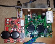
Just for kicks, compare the implementation of one basic chipamp design (right side in first photo) and a couple examples of the current state of LM3886 development.
So I say - jump in wherever you feel comfortable.
Attachments
Last edited:
100 % agree . Nice to get a balanced argument . I had no idea about TDA 7294 and it might fit an industrial application I am working on . LAB 47 is highly respected and I feel can be called hi end , as far as I know it still is a chip amp ? That should say cake mix amps can be very good . Gain Clones are a bit above what I want to build right now. One can beef up PCB's to be almost the same thing .
One of the most attractive and valuable assets of this forum is the ability for new members to enter at any level and still receive excellent support and shared knowledge to complete a useful and safe project.
Useful and safe: A Philips car chip. Car alternator voltage is 14.4vdc to 14.8vdc, and those car chips can run on a 15vdc Toshiba laptop replacement power pack, which are very inexpensive.
With the power supply safely sealed away in a plastic box, and with the much lower voltage, the 1st time builder would be much safer than playing with transformers.
P.S.
I'm actually building that project this weekend for a cute little TV amp, and yes it will be point to point.
Philips doesn't mention exactly how to do the mute; however, 10k to v+ will do it.
Last edited:
For car chip: Toshiba Adapter 15v 90w SMPS (most favorable model has a 2-prong cord).
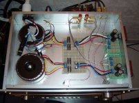
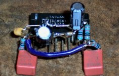
Attached Photos is one of the Philips car chips done point to point.
Most of the details are in the datasheet, but here's the build method:
Power pins are close to the chip face, ground pins are in the middle row, 100n||22u caps are inbetween power and ground (the rails pictured are horizontal across the chip), and signal pins are the bottom row. Basically, the power stuff is moved up top, the signal stuff is moved down below. I put 2,200u at the DC power jack for reserve capacity (and bass). 100u is installed as indicated by the datasheet. Mute/mode and detector (if present) are connected to V+ via 10k resistors to allow playback. Wima 33n polyester caps are attached to the inputs. 10k caps are between the 33n caps and signal ground for input load. With this, one can unplug the audio cable and the amp is dead silent--no buzz. Heck, it takes longer to explain than solder it.
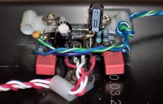
The next photo is tie-down and hookup. I hadn't hooked up the power cable when I made that picture, but its done now and rockin the house.
Well, it is rockin out the house because I gave it 800u output caps to help the sealed box speakers thunder nicely. Applicable range is 800u to 4400u, depending on the size of the speakers. Of course the DC offset is zero. The series caps also conserves the amplifier output power by not sending 20hz that these speakers wouldn't reproduce anyway. And that's the deal if you want chest thumping bass from a car chip driving little sealed box speakers. Yes, its louder than heck and both clearer and cheaper than anything at Best Buy. Kudos to Philips. Cheers!
Attached Photos is one of the Philips car chips done point to point.
Most of the details are in the datasheet, but here's the build method:
Power pins are close to the chip face, ground pins are in the middle row, 100n||22u caps are inbetween power and ground (the rails pictured are horizontal across the chip), and signal pins are the bottom row. Basically, the power stuff is moved up top, the signal stuff is moved down below. I put 2,200u at the DC power jack for reserve capacity (and bass). 100u is installed as indicated by the datasheet. Mute/mode and detector (if present) are connected to V+ via 10k resistors to allow playback. Wima 33n polyester caps are attached to the inputs. 10k caps are between the 33n caps and signal ground for input load. With this, one can unplug the audio cable and the amp is dead silent--no buzz. Heck, it takes longer to explain than solder it.
The next photo is tie-down and hookup. I hadn't hooked up the power cable when I made that picture, but its done now and rockin the house.
Well, it is rockin out the house because I gave it 800u output caps to help the sealed box speakers thunder nicely. Applicable range is 800u to 4400u, depending on the size of the speakers. Of course the DC offset is zero. The series caps also conserves the amplifier output power by not sending 20hz that these speakers wouldn't reproduce anyway. And that's the deal if you want chest thumping bass from a car chip driving little sealed box speakers. Yes, its louder than heck and both clearer and cheaper than anything at Best Buy. Kudos to Philips. Cheers!
Attachments
Would this be worth considering ?
The 5532 OpAmplifier, part 1 - ELEKTOR.com | Electronics: Microcontrollers Embedded Audio Digital Analogue Test Measurement
The 5532 OpAmplifier, part 1 - ELEKTOR.com | Electronics: Microcontrollers Embedded Audio Digital Analogue Test Measurement
And, then there's this:
LM1875 Power Amplifier Assembled Board LM1875T | eBay
It is assembled, so we'd miss out on some soldering practice. However, there's still plenty to do for casework, like heatsink (thermal pads, shoulder washers), transformer, speaker jacks, small signal routing, and an enclosure with useful ventilation both above and below the heatsink.
However, if one needed soldering practice, here's plenty:
http://www.ebay.com/itm/Kit-for-GAI...ier-board-speaker-protection-SC-/200826815903
Last edited:
I remember year ago LM1875 held up as an example of where chip amps were able to compete " proper amplifiers " .
Here is an even simpler way .
ILP HY60 30 WATT POWER AMPLIFIER MODULE items in ILP Direct Ltd store on eBay!
Here is an even simpler way .
ILP HY60 30 WATT POWER AMPLIFIER MODULE items in ILP Direct Ltd store on eBay!
- Status
- This old topic is closed. If you want to reopen this topic, contact a moderator using the "Report Post" button.
- Home
- Amplifiers
- Chip Amps
- Basic