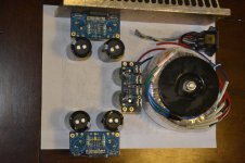
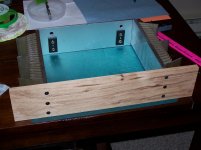
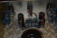
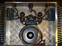
Hey everyone I am finally getting started on my LM4780 Dual Parallel project.
I have gone with AudioSector LM4780 kits and will be running them on a single power supply.
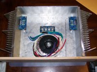
I am running an Antek AS-2224 Toroid, I know the voltage will be a little high but I have been running on a chip in stereo on it for about a year without any issues and a MUCH smaller heatsink.
I am currently deciding on power supply setup, CRCLC or 10kuf "snubberized" with additional 10kuf tank capacitance at the amp boards.
The project is progressing slowly but well.
Any thoughts about my power layout?
I have gone with AudioSector LM4780 kits and will be running them on a single power supply.
I am running an Antek AS-2224 Toroid, I know the voltage will be a little high but I have been running on a chip in stereo on it for about a year without any issues and a MUCH smaller heatsink.
I am currently deciding on power supply setup, CRCLC or 10kuf "snubberized" with additional 10kuf tank capacitance at the amp boards.
The project is progressing slowly but well.
Any thoughts about my power layout?
Attachments
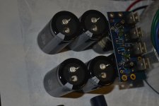
Audiosector, run by Peter, has a philosophy of only using at amplifier smoothing and only using relatively low values of electrolytics here.
A bit like oversized MF decoupling right at the amplifier, where most would use 100uF to 220uF, Peter advocates around 1500uF for best overall sound quality.
But he does not use conventional smoothing capacitance at the transformer/rectifiers.
Your proposed arrangement is completely at odds with Peter's philosophy and yet you have bought into his product.
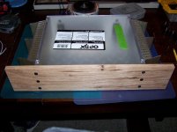
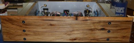
Top & Bottom Installed
The top & bottom are installed with spacing for ventilation.
The bottom is 1/8" Diamond Plate and the top is .093" PlexiGlass.
I put the top on spacers for ventilation.
The diamond plate is installed with the tread upward.
This allows for an evenly spaced gap all down both sides for good natural cooling.
Attachments
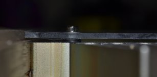
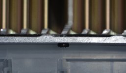
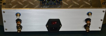
Rear Panel Completed
I was lucky enough to get my cut for the IEC Socket to work out perfectly.
I had to use my bandsaw to make the cutout because my 50's Dremel scrollsaw just wouldn't cut 1/8" aluminum.
Luckily enough the opening cut with the bandsaw is completely covered by the bottom bezel of the IEC Socket.
I was lucky enough to get my cut for the IEC Socket to work out perfectly.
I had to use my bandsaw to make the cutout because my 50's Dremel scrollsaw just wouldn't cut 1/8" aluminum.
Luckily enough the opening cut with the bandsaw is completely covered by the bottom bezel of the IEC Socket.
Attachments

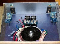
It has been playing music on my sacrificial speakers for about an hour now and those heatsinks are barely warm to the touch.
After I'm satisfied they won't blow up my nice speakers I will hook them up and see how it does bass.
I had the left chip configured as stereo for quite a while and really enjoyed it.
I have always been itching to get the full Dual Parallel going for over a year now.
After I'm satisfied they won't blow up my nice speakers I will hook them up and see how it does bass.
I had the left chip configured as stereo for quite a while and really enjoyed it.
I have always been itching to get the full Dual Parallel going for over a year now.
- Status
- This old topic is closed. If you want to reopen this topic, contact a moderator using the "Report Post" button.
- Home
- Amplifiers
- Chip Amps
- LM4780 Dual Parallel Project