love the ingenuity and has geek factor for miles, but you'll excuse me for saying that it doesnt appear to be very shoebox sized, the F5 in particular I think could be made smaller passively. at the same time, i'm pretty sure you have more dissipation capacity than what is needed for an F5 or even F5 turbo? one note, isnt plexiglass a static risk?
photos are unnecessarily huge, I have 100MBit cable so no problem for me, but others may not be so impressed, there is no detail shown in the large pics that couldnt be shown smaller, you just havent resized them small enough from what was spat out from the camera.
I didn't say it was shoebox sized. In my aleph 1000 thread I discovered that for us diy'ers who have a couple of bucks around. If you buy 2 genysys power supplies, you are set for amp building for life. No more caps, no more torroids. A garden hose and d6 hydroblocks (they are real nice as they use copper pads) And your imagination... The aleph 1000 will burn 4500w per channel in heat, now the whole amp fits in a rack, and you can carry it and the power supplies and the garden hose if you use the genysys 2u (that they dont make yet 2u 200-25). Leakproof hose connections a must. Rock On
.....it doesnt appear to be very shoebox sized, the F5 in particular I think could be made smaller passively. at the same time, i'm pretty sure you have more dissipation capacity than what is needed for an F5 or even F5 turbo? one note, isnt plexiglass a static risk?
photos are unnecessarily huge, I have 100MBit cable so no problem for me, but others may not be so impressed, there is no detail shown in the large pics that couldnt be shown smaller, you just havent resized them small enough from what was spat out from the camera.
The size was selected as a mid-point. There are obviously more screw terminals than necessary but they allow for experimenting with a variety of cooling blocks and amp PCB sizes. The final target has always been those massive "Burning Amp" builds, but I'm working up to that and learning as I go. My first attempt was a grand overshoot for a LM3886 build that had several folks scratching their heads - have to start somewhere
")
Static risk? - The earth/chassis ground, PS CL-60 and chassis to Plexiglas screw are all within about a 3/4" space. As mentioned, a strap may be added later.
Great point on the pic sizes. I never gave a thought to readers with slower access. I'll adjust accordingly. I used an off-site service because I wanted to do a full pictorial in one chunk. I prefer the "thumbnail" system here on the forum but there are limits on uploads and post sizes. The FAQ describes a "draft post" function but I couldn't find the buttons to turn it on. Maybe the forum admins can follow up on that. Might try a blog next time.
A lesson from IBM's TCM Thermal Conduction Module water-cooled mainframes .......... They seal both ends when you unhook them..............There's all kinds of brass disconnects made for hydraulics which seal both sides........ I know I got them cheaper from somewhere, probably Street & Competition Inc. .........
I considered using these but the emphasis for this version was eliminating as many hoses as possible. The next build features a Mustang heater core as the heat exchanger and will most likely be modular with an umbilical between amp and cooler.
I think I'd favor construction which had a solid wall between the wet side and dry side in a stack of amps, and put the power and the heat exchanger into separate boxes.
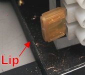
It doesn't show well in photos, but there is a lip on the floor of the PS lower bracket. I considered seperate compartments but went with an open bottom under the pump/tank/radiator section. There will be a low profile stand under the amp with four standoffs that aid air flow and allow potential leaks to fall away from the amp and PS module.
A TIG welder would also serve you well, but you need a pretty big one for welding aluminum because it conducts the heat away. ...........I'm lucky and they guy next door is a true artisan with a big TIG in his garage, wonderful with aluminum and stainless etc.
I'm jealous
. My Mustang fanatic buddy and I pooled our funds and bought a TIG. Sadly it doesn't have the juice nor gas bath to do a good job with aluminum. Works great for amp chassis and transformer shields/cans though.Thanks so much for your comments. Stay tuned....
Attachments
Last edited:
n3szd: I was talking to bcmbob... who did mention shoebox.
I just thought it was an odd construction to picture together with an F5, which could easily be done smaller passively. no switchmode power supply will last anything close to life, thats the main disadvantage of them currently, toroids and caps will last a very long time indeed, toroids will last a lifetime, caps not so much. switchmode, maybe 5-7 years MAX. dont get me wrong I feel switchmode supplies have a lot of advantages, i'm using some DPS600 fully regulated high current supplies for my amps (not easy to do for poweramps) and they are excellent, but the performance and size are the advantage, long life is not.
bcmbob: yes static risk, not for death, but for mosfet ESD death/damage. plexi can build up static depending and with fans I thought it might make for conditions that didnt help. that was just a query, not a statement, I would avoid it for an amp but its probably fine.
as for posts yes, even now the page was a bit annoying to load. you can add up to 10 or so pics at a time, click the 'go advanced' button in the edit mode. also linking offsite images is not looked on well, because hosting sites change, links get broken etc and then you end up with a meaningless post without the pics.
Last edited:
n3szd: I was talking to bcmbob... who did mention shoebox.
I just thought it was an odd construction to picture together with an F5, which could easily be done smaller passively. no switchmode power supply will last anything close to life, thats the main disadvantage of them currently, toroids and caps will last a very long time indeed, toroids will last a lifetime, caps not so much. switchmode, maybe 5-7 years MAX. dont get me wrong I feel switchmode supplies have a lot of advantages, i'm using some DPS600 fully regulated high current supplies for my amps (not easy to do for poweramps) and they are excellent, but the performance and size are the advantage, long life is not.
I'll take the 5yr warranty from the factory.. Just me. In 3ph and real high power torroids and caps are cheaper, single phase turns it into a mess.
......yes static risk, not for death, but for mosfet ESD death/damage. plexi can build up static depending and with fans.....
as for posts yes, even now the page was a bit annoying to load...... hosting sites change, links get broken etc and then you end up with a meaningless post without the pics.
O.K. - you've pushed me over the edge
I'll add the braided copper strap.I used Photobucket which will probably be stable for a long time. I had the post almost complete using the method you describe - with all the pics uploaded to the gallery. This new process was fun but probably a toss up for functionality. Check back later this evening when the adjustments should be complete.
Thanks....
O.K. - you've pushed me over the edge
I used Photobucket which will probably be stable for a long time. I had the post almost complete using the method you describe - with all the pics uploaded to the gallery. This new process was fun but probably a toss up for functionality. Check back later this evening when the adjustments should be complete.
Thanks....
no actually I dont mean adding to the gallery. give me a moment i'll take some snapshots of the process
haha
cool its just a precaution, the only other option is to use metal, wood or some sort of ESD safe polymer. yes photobucket is longer lived, but even they will change their servers every now and then, it takes a while but most of these links die eventually. you can add a further set of pics, you can just only add a limited number in one go.
see it adds them all along the bottom like this though and you click on them to enlarge. you get to this by 'go advanced' see the paperclip button? thats the attach button, you will then get the dialogue with the list, you select up to 10 images from your computer at a time, hit upload, once its uploaded it clears the list and you can add another 10.
Attachments


Bob,
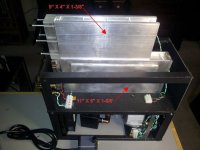
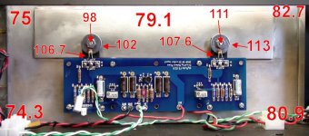
Very nice work on this heat exchanger concept, and great to see all the cool hardware. I see you are using what were once air cooled finned heatsinks on the liquid side of your MOSFET mounts. It provides a lot of surface area enhancement which is needed when working with air as the cooling medium but I am not sure you need fins on the water-cooled side - unless your flow rates are very very small, but looks like you are using at least a 1 gpm aquarium pump. The thermal conductivity of liquid water is about 1000x greater than air (due to density mostly and also water is a great heat absorber) and really all that is needed is a simple channel. If you wanted to improve heat transfer inside the channel, stuff some stainless steel wool in it to provide turbulence and increase residence time of water. A simple 6 inch long 2 in x 2 in aluminum block with a half inch hole drilled through the length can remove probably circa 1 to 2 kW of heat. For example for a 5 deg temp rise in water temp with a circa 1 gpm pump or a 4 liter/min pump is 4000 cc/min x 4.2 J/cal deg C x 5 deg = 84000 Joules. 84,000 J/60 sec/min = 1400 watts. From my experience, a 6 inch channel with straight hole can raise temp of water by 5 deg C easily. I think F5 puts out 500 watts excess heat so there is plenty of margin.
Very nice work on this heat exchanger concept, and great to see all the cool hardware. I see you are using what were once air cooled finned heatsinks on the liquid side of your MOSFET mounts. It provides a lot of surface area enhancement which is needed when working with air as the cooling medium but I am not sure you need fins on the water-cooled side - unless your flow rates are very very small, but looks like you are using at least a 1 gpm aquarium pump. The thermal conductivity of liquid water is about 1000x greater than air (due to density mostly and also water is a great heat absorber) and really all that is needed is a simple channel. If you wanted to improve heat transfer inside the channel, stuff some stainless steel wool in it to provide turbulence and increase residence time of water. A simple 6 inch long 2 in x 2 in aluminum block with a half inch hole drilled through the length can remove probably circa 1 to 2 kW of heat. For example for a 5 deg temp rise in water temp with a circa 1 gpm pump or a 4 liter/min pump is 4000 cc/min x 4.2 J/cal deg C x 5 deg = 84000 Joules. 84,000 J/60 sec/min = 1400 watts. From my experience, a 6 inch channel with straight hole can raise temp of water by 5 deg C easily. I think F5 puts out 500 watts excess heat so there is plenty of margin.
Hey X,
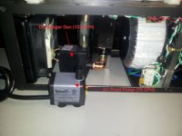
Lots of good useful information. Lets me know I have lots of room to downscale later versions and still maintain efficiency. This pump (Danger Den DD-CPX1) is capable of 132 GPH but won't run at anything near full speed. I have two new AC pond pumps to try - the smallest rated at 75 GPH @ 1 foot. Still lots of room to play with.
I am considering using just one finned panel mated to some 1/4" flat stock as one alternative, and a sandwich of flat stock with a snaking path cut with an overhead mill. Have to figure a way to worm my way back into the training center shop at my former employer.
Like the stainless steel wool idea. Sounds more useful and simpler than plugging and adding holes to control the flow rate and path. I'll try it with the smaller cooling block.
Attachments
Bob,
The heat removal liquid to air xchanger may be the limiting point. That needs to be sized greater than heat output you need to remove. Have you considered heat pipes mounted to aluminum blocks for mosfets and fins with fans on the removal end? Computer cpu heatsinks often use heatpipes and are cheap. Cpus are about 100 watt max so one for each mosfet? Of course one can build diy heat pipes from copper pipe, distilled water and stainless steel wool.
The heat removal liquid to air xchanger may be the limiting point. That needs to be sized greater than heat output you need to remove. Have you considered heat pipes mounted to aluminum blocks for mosfets and fins with fans on the removal end? Computer cpu heatsinks often use heatpipes and are cheap. Cpus are about 100 watt max so one for each mosfet? Of course one can build diy heat pipes from copper pipe, distilled water and stainless steel wool.
Last edited:
I would hate to clean off the oil everytime I had to fix or repair a part. Interesting conversation piece but there is not enough heat to need to cool it like a substation transformer. Btw, high quality mineral oil isn't cheap. If the components were cleaned so that they had no salt residue, pure distilled/de-ionized water can be used as a coolant. Although parts need to be rust-free. This is done to cool HV flash lamps in big laser systems. The pure water doesn't conduct electricity even for 3000 volt discharge lamps.
Sorry, No oil and no liquid nitrogen
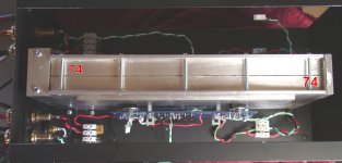
Just fired up about an hour ago. The cooling system is working thought not yet uniform. The fluid isn't reaching the right side at full flow. I'll use some of X's steel wool to adjust. There is a small gap between the halve which is probably leaking by more than I had planned.
Only using a Walkman as source and and the IR gun for readings so far. Later I'll add a pre and use the thermocouple for more accurate readings. The fan and pump (both 12 VDC) are powered by a single 7.5 1A wallwart "Y"ed to sockets. Totally silent at one foot. I'll do a recording and post a link.
So Far So Good. Room temp was 70 F for tests.
Attachments
Last edited:
Nice work Bob. It looks like a water cooled laser power supply more than an audio amp! Here is what I was telling you about how efficient water cooling is. There are like 20 TO3 power transistors on this laser power supply which as I recall rejects a boatload of heat as the thing is 240vac 3 phase at 30 amps. Just a simple aluminum block with some copper tubing bonded to it.
An externally hosted image should be here but it was not working when we last tested it.
Sharp Right Turn !!
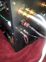
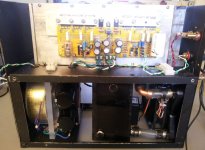
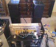
In the process of redesigning/compacting the cooler for the F5 so I put the Honey Badger clone on-board. Been running all afternoon and water block hasn't moved above room temperature. I've been distracted by a speaker project so no flow/fan readings yet. As they say in the software world "Real soon now"
The amps are pushing the Coppers from PE DIY. Nice combo! No Leaks!
Attachments
- Status
- This old topic is closed. If you want to reopen this topic, contact a moderator using the "Report Post" button.
- Home
- Amplifiers
- Chip Amps
- Liquid Cooling Build