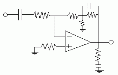
ok, i had an idea, but no real way to test it right now. basically it is a classic inverting amplifer, but with a high input impedance (BTW, what is the input impedance of the lm3875? like 1M or so?) in any case it uses a 100k input resistor and then uses the 3 resistors in the feedback path, making a t with the middle resistor tied to ground (i'll try to make a pic). the purpose is to allow a high input impedacne for the RC filter on the input to allow for a small value cap like a polystyrene cap (i have plenty of em!) to be used. the 100k would be the limit i'd like to see on the max value of the input resistor. the 3 resistors in the feedback path allow for more gain without resorting to really high value resistors.
this could likely be driven from any source including a dual-triode ltp. not sure if such would improve the sound at all, but it makes even that a possibility. the only concern of mine is the feedback ground point and if it should be a seperate ground wire or not. i assume it would not necessitate such though.
this could likely be driven from any source including a dual-triode ltp. not sure if such would improve the sound at all, but it makes even that a possibility. the only concern of mine is the feedback ground point and if it should be a seperate ground wire or not. i assume it would not necessitate such though.
Resistor to ground ?
I don't know how you figured out this circuit but taking a resistor to ground reduces the take off point for the feedback. And what does the capacitor do. If it shorts out the resistor it is across , well.....................
To get a high input resistor , you cannot juggle the feedback like you have shown. The current through the input resistor has to flow through the feedback resistor. If you increase the value of the feedback resistor ( within practical useable values) the gain goes up and if you reduce it , the gain goes down. Besides the input resistor is also a contributor to noise . So a larger resistor will only degrade the S/N ration of the amp.
To achieve what you want , a large input resistor , keep the feedback resistor ( single resistor) also high. I see 1Meg on the LM3886 so you could try something like that. That will give you a gain of just 10. The remainder can come from the preceeding ( tube?) stage.
Cheers.
the resistor to ground is to make a high equivilent impedance for the feedback without using resistors greater then the input resistor. the cap shorts out one of the resistors at RF, limiting the RF gain. obviously the feedback impedance must be at least an order of magnitude greater then the input inpedance. in order to use very small value caps like say 39nF polystyrene caps, the input resistor has to be large as well.
"So a larger resistor will only degrade the S/N ration of the amp. "
-yeah, that's why i wanted to keep the resistance high, but not "too-high". the design is made to allow for low value capacitors on the input.
"So a larger resistor will only degrade the S/N ration of the amp. "
-yeah, that's why i wanted to keep the resistance high, but not "too-high". the design is made to allow for low value capacitors on the input.
a single resistor would have to be 10 times as high as the input. this is a minimum, and will mean using a noisier resistor. the cap is optional and could likely be placed in other spots, i didn't give too much thought to it. the major point was to allow for high impedance input for a small cap.
Re: Resistor to ground ?
it is essentially the bootstrap circuitry used in some amps to produce very high (ac) impedence.
ashok said:And what does the capacitor do.
Cheers.
it is essentially the bootstrap circuitry used in some amps to produce very high (ac) impedence.
An externally hosted image should be here but it was not working when we last tested it.
A few people are having trouble understanding Chris's circuit, so I took the liberty of redrawing it a little.
Anyway, R1 and R2 form the familiar feedback network for an inverted circuit. R3 and R4 add a voltage divider that isn't usually there.
If you added R3 and R4 to an existing circuit, the gain would increase by the factor of the voltage divider. Then, to get the gain back to the original value, you can reduce R2. That's what Chris is going after.
-- Dave Cigna
miguel2 said:Hi,
Can you put a schematic of it? I cant clip my IGC with the EF86 pre, so an higher input impedance would be nice. I have no pot on the IGC, just a 100K to ground on the input. But dont know what is the input impedance of it
Miguel
is igc for "inverting gain clone"? if so the input impedance will usually be the resistor before the inverting terminal. if so, then the 100k is more then the actual input impedance, and this is likely whatever the first resistor is (R1 in the circuit below). this would probalby be something like 10-47kohm. i know some ltp tube designs aren't happy with less than 47k.
s igc for "inverting gain clone"? if so the input impedance will usually be the resistor before the inverting terminal. if so, then the 100k is more then the actual input impedance, and this is likely whatever the first resistor is (R1 in the circuit below). this would probalby be something like 10-47kohm. i know some ltp tube designs aren't happy with less than 47k.
Yes, it is an inverted GC. The resistance I use before the - input is 10k, so the input impedance is 10k? That iss well bellow the optimum value for my preamp (70 - 80k).
Another way to tuen this: what is the input impedance of a non-inverted circuit?
Miguel
- Status
- This old topic is closed. If you want to reopen this topic, contact a moderator using the "Report Post" button.
- Home
- Amplifiers
- Chip Amps
- modified small cap gainclone