To balance the two inputs, the FB resistor (at -in) will usually be equal to the other resistor (at +in). The resistor at +in is connected to ground. The higher the resistance, the better the noise floor, as can be seen in simulators.
Beside lifting the input impedance, it is often mentioned in "Design Example" of a chip datasheet to use such a high resistance (usually mentioned as 100k) to lower output offset.
I have tested many resistance and the offset differences are not big. Even the lowest offset was not the best sound to my ears.
But with FB resistance as high as 100k you can get away with 4u7 MKP in the FB path. May be it is audible if compared with low quality electrolytic? (mine was BG, so no worse)
Hi Jay,
I'm not expert in electronis just hobby. The 4u7 MKP , is it input capasitor ?
Hi Jay,
I'm not expert in electronis just hobby. The 4u7 MKP , is it input capasitor ?
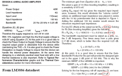
It is to replace the 22uF on the feedback loop in your diagram. The lowest frequency you can get is a factor of RC (of the feedback 100K {or 8k2} and 22uF). The bigger the R, the lower you can use the C.
100k is very high, so you can use smaller C, around 4u7 based on calculation on the datasheet (attached). Too low than that, bass will never reach 20Hz, but slightly lower is okay, often will give better sound when the speaker doesn't have the ability to produce as low as 20Hz.
If you use MKP WIMA or Philips, 4u7 is about 3cm. But you don't need higher than 5V for the capacitor so if you can find capacitor with low voltage rating, even if the capacitance is big, the size is also small.
Sanyo OSCON (or other computer grade caps) for example, has many caps rated at 10v.
Attachments
Last edited:
These boards are available from KOBA Electronics in Singapore in Chinatown area. Can find info on the location here Koba Electronics
you can get a complete 2 channel kit for S$35 ... I have 4 of them for an 8 Ch setup to drive my LS521's
you can get a complete 2 channel kit for S$35 ... I have 4 of them for an 8 Ch setup to drive my LS521's
The link was for the company address...they don't really have a web site for a store/purchases
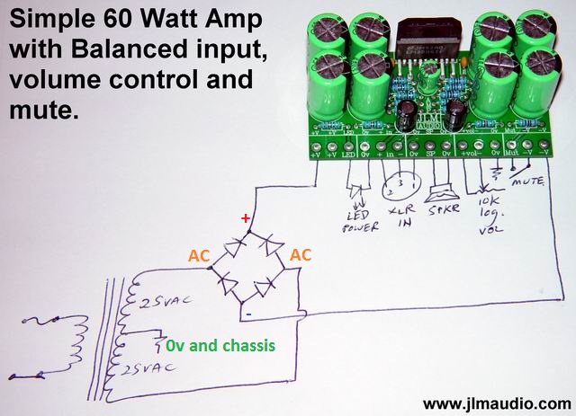
it can be used BTL as RCA or balanced input or stereo with 2 RCA inputs. I use 4 of them in the stereo mode, but I have also used in BTL mode as both balanced and rya input options.
you could also check out this place as they have single modules that can be used also in BTL with multiple boards.
http://www.jlmaudio.com/shop/ but site is down at this time I checked...normally its up and Joe ships internationally too as complete kits or just boards.
the build log is here JLM AUDIO • View topic - JLM 60Watt Power AMP Kit which oddly is up
I want to continue assemble this amp. I got a nice box . But after I check there is not enough space for adequate transformer. I wll put in 4 x LM3886 as stereo, each channel has parallel of 2 pcs.
I'm thinking to use phase inverter (sorry I'm not sure this is the right termination) in order to get efficiency of psu. Does anybody have experience with phase inverter ?
I'm thinking to use phase inverter (sorry I'm not sure this is the right termination) in order to get efficiency of psu. Does anybody have experience with phase inverter ?


The height of box is limited factor for big transformer. I can't find big wattage toroid with low voltage here, most of them up to +/- 24 -55 volt. So maybe I use 400 watt smps to supply this chip.
Now I have 1 transformer +/- 25 volt only 6 A can fit into this casing, or 400 watt smps.
Any suggest which one should I use ?
If use transformer I plan use phase inverting.(?! )
That's a 300VA transformer..........The height of box is limited factor for big transformer. .................
Now I have 1 transformer +/- 25 volt only 6 A can fit into this casing, ...........
It can power a group of chipamps up to a total of 300W of maximum output power.
For better performance you may find that limiting the maximum total output power to 200W sounds a little bit better.
Some builders will claim that 150W of total maximum output should be the limit for high quality performance.
The maximum power from an lm3886 working with a 25+25Vac transformer is ~50W.
That allows 1 to 6 of these chipamps to be powered by your 300VA transformer.
Why is your chassis height a problem?
For power supply I have Elco Elna Gold 12000 microF/50volt = 4 pcs and 2 LM338 for regulator. I tried LM338 this morning (in my country is holiday) , but unfortunatelly the IC just blew . Eventhough I bought it from well known electronic component shop . Only this shop sells LM338 and LT1083. It looks I got the fake one.
From data sheet : pin1=ajust; pin2=out; pin3=in


I will not buy it again , maybe I will parallel 5-6 pcs of LM337 , LM317 ; or use 2N3005 or without regulator.
From data sheet : pin1=ajust; pin2=out; pin3=in


I will not buy it again , maybe I will parallel 5-6 pcs of LM337 , LM317 ; or use 2N3005 or without regulator.
The boards you are using are ok up to around +/- 35vdc and you should NOT use any regulators, h
Just a 25A 400V bridge and some good filter caps and bypass with 0.1uF across the diodes and filter caps (snuberised) with maybe a 10-50uF electro as well. This should give you around 33-35vdc for the amps
Run all your grounds to one point at the caps grounds in the transformer ct
Just a 25A 400V bridge and some good filter caps and bypass with 0.1uF across the diodes and filter caps (snuberised) with maybe a 10-50uF electro as well. This should give you around 33-35vdc for the amps
Run all your grounds to one point at the caps grounds in the transformer ct
the chipamp specification is <=+-42Vdc with signal present.
The chipamp heats more with a load connected.
As the load resistance or impedance goes down, the current being delivered goes up. This results in a 4ohm chipamp running hotter than an 8ohm chipamp and both will be hotter than a 16ohm chipamp.
For heating and reliability reasons the recommended supply voltage is changed for different load impedances.
+-40Vdc for 8ohms and +-30Vdc for 4ohms.
These voltages droop considerably when delivering maximum power for longer than a few milliseconds, typically by 2V to 5V. This supply rail droop helps to reduce the temperature that the chipamp operates at.
The reduced supply voltages below the specified +-42Vdc is a reliability issue.
Generally one requires the amplifiers to run with the highest supply voltage they can accept and remain reliable. That higher supply voltage reduces the amount of time that the signal is being distorted by clipping of the output.
For power supply I have Elco Elna Gold 12000 microF/50volt = 4 pcs and 2 LM338 for regulator. I tried LM338 this morning (in my country is holiday) , but unfortunatelly the IC just blew . Eventhough I bought it from well known electronic component shop . Only this shop sells LM338 and LT1083. It looks I got the fake one.
From data sheet : pin1=ajust; pin2=out; pin3=in
Did you place any of these caps after the regulators? LM338 is 5A max.
- Status
- This old topic is closed. If you want to reopen this topic, contact a moderator using the "Report Post" button.
- Home
- Amplifiers
- Chip Amps
- LM3886 unussual pcb