Hello!
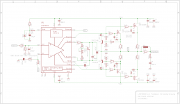
I designed a LME49830 with foldback current limit and the popular 2sk1530/2sj201, the circuit is similar to the an1850 from ti.
Unfortunately I can only simulate the circuit in tina-ti because I don't have the LME in lt-spice. BUT I don't have the 2sk1530 mosfets in tina-ti So I tried to simulate it with irfp240 and irfp9240 and it nearly worked. The only thing were the low distortions on the takeover point but I think it is because of wrong bias current and the "wrong" mosfets in the simulation. The current limitier worked very well
So now, a question to the specialists here in the fomum, will this amp work??
Is it a good idea to take the expensive 2sk1530 / 2sj201 mosfets instead of the cheaper irfp240 / 9240?
Thanks in advance ;-)
regards
bernhard
I designed a LME49830 with foldback current limit and the popular 2sk1530/2sj201, the circuit is similar to the an1850 from ti.
Unfortunately I can only simulate the circuit in tina-ti because I don't have the LME in lt-spice. BUT I don't have the 2sk1530 mosfets in tina-ti
So I tried to simulate it with irfp240 and irfp9240 and it nearly worked. The only thing were the low distortions on the takeover point but I think it is because of wrong bias current and the "wrong" mosfets in the simulation. The current limitier worked very well So now, a question to the specialists here in the fomum, will this amp work??
Is it a good idea to take the expensive 2sk1530 / 2sj201 mosfets instead of the cheaper irfp240 / 9240?
Thanks in advance ;-)
regards
bernhard
Attachments
Last edited:
I built it
I finally built that circuit above with only one pair of mosfets and it worked. I had some problems with oscillations at the beginning, it is very important to have only one big gnd point. After I changed this the oscillations were gone
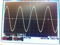
So can't say anything about the sound quality because my testspeaker is very bad but I measured it.
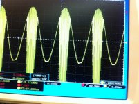
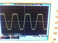
The current limiter needs a bit tuning, the negative side seems to limit correctly but the positive side looks very very strange.
I tested it by putting a 2R4 Ohms resistant from output to gnd.
Supply voltage was +/- 60V. The Voltage at the gate of 2sk1530 was 1,758V and on the 2SJ201 it was -1,537. After putting the 2R4 Ohms at the output the voltage at the 2sk1530 was 1,501V and on the 2SJ201 it was -0,499V.
So it doesn't work simultaneously
I added two pictures, one of normal operating mode and another with the resistant at the output.
Anyone any suggestion what to change?
I finally built that circuit above with only one pair of mosfets and it worked. I had some problems with oscillations at the beginning, it is very important to have only one big gnd point. After I changed this the oscillations were gone
So can't say anything about the sound quality because my testspeaker is very bad but I measured it.
The current limiter needs a bit tuning, the negative side seems to limit correctly but the positive side looks very very strange.
I tested it by putting a 2R4 Ohms resistant from output to gnd.
Supply voltage was +/- 60V. The Voltage at the gate of 2sk1530 was 1,758V and on the 2SJ201 it was -1,537. After putting the 2R4 Ohms at the output the voltage at the 2sk1530 was 1,501V and on the 2SJ201 it was -0,499V.
So it doesn't work simultaneously
I added two pictures, one of normal operating mode and another with the resistant at the output.
Anyone any suggestion what to change?
Attachments
Last edited:
Q2 and Q3 shouldn't be necessary with the LME49830.
Some other stuff -- 1) the gate stopper resistors should be mounted as close as possible to the gates of the MOSFETs. 2)Increasing the value of the compensation capacitor will reduce the slew rate and may be necessary with some devices.
Some other stuff -- 1) the gate stopper resistors should be mounted as close as possible to the gates of the MOSFETs. 2)Increasing the value of the compensation capacitor will reduce the slew rate and may be necessary with some devices.
DC and very long duration limiting must respect the DC SOA of the devices.
But, transient peaks far exceeding the DC SOA must be allowed to pass unhindered.
You need to modify your limiting to allow medium term and short term and very short term transient demand currents to pass.
But, transient peaks far exceeding the DC SOA must be allowed to pass unhindered.
You need to modify your limiting to allow medium term and short term and very short term transient demand currents to pass.
It's a bit sad that I can't simulate it with this fets.
On the first step I will change R13 and R14 (the current resistors) from 0R22 to 0R10, then the current circuit will limit much later.
In my testcircuit I used 1N4007 for D1 and D2 because I don't have shottky diodes. Would it be better to replace them with shottky diodes? If yes, what will be the advantage?
It would probably be safer to keep the DC current limit low or very low while you experiment with limier component values.
That last thing you want is to blow up your amplifier because the limiter came in a bit late.
Can you arrange in your circuit for the limit to reduce as heatsink temperature rises?
That last thing you want is to blow up your amplifier because the limiter came in a bit late.
Can you arrange in your circuit for the limit to reduce as heatsink temperature rises?
My DC supply limits the current at 2,5A.It would probably be safer to keep the DC current limit low or very low while you experiment with limier component values.
That last thing you want is to blow up your amplifier because the limiter came in a bit late.
Yes, that's right!
Can you arrange in your circuit for the limit to reduce as heatsink temperature rises?
Sorry I didn't understand this sentence...
Does it mean that I should use a ntc in my current limit circuit?- Status
- This old topic is closed. If you want to reopen this topic, contact a moderator using the "Report Post" button.
- Home
- Amplifiers
- Chip Amps
- LME49830 with Foldback Current Limit and 2sk1530