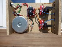
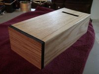
Hi, I am new to the community and just built my first chipamp. A LM3886 stereo kit from chipamp.com. I followed all instruction and did not install the Ci cap. I use a 400va 2*24v toroid. I've put everything together on a piece of wood for testing purpose. I like the sound of the amp very much. It is detailed, kinda smooth, but powerful.
Here are my two questions.
Firstly, DC offset is 126mv on one channel and 97mv on the other. Do I need to worry? Have I made a mistake ?
Secondly, I hear a slight hum with my ear to the speaker. 10 inches away from the speaker it is inaudible. Again, do I need to worry? Have I made a mistake?
Any input is appreciated.
Regards from Switzerland.
Michael
Attachments
I use a little external box, a line driver, which has an Alps pot.: ABACUS electronics | Line Driver variable
The line driver has one input, to which an Airport express is attached at the moment. But the hum is the same with or without the line driver attached.
The line driver has one input, to which an Airport express is attached at the moment. But the hum is the same with or without the line driver attached.
Remove the input wires and short the inputs with a 1/2" wire. This will eliminate external hum sources from the inputs, to determine the hum source. Used a hand drill to twist the speaker wires, the twisted wires limit noise going into the amp. from external sources. Twist the input, output and speaker wires at one twist per 1/2". Move the orange and gray transformer wires away form the amp.
I have not used the Ci capacitor, as the instructions said it is optional.
Try whit it.
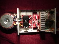
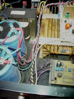
This is a monoblock but the goal was to make all wires as short as possible. I didn't install Ci and both amps are dead silent. You might get better results with a metal chassis.
There is always the phantom of nearby noise generators with longer internal untwisted wiring. Check for light dimmers, halogen and neon lamps in the area. Try a diferent location or a different room. I get some noise when the amps are near a computer/monitor..
Also check section 1.7 in the user guide for optional placement of R3. You might consider swapping that placement
Attachments
Last edited:
Thanks a lot guys. As I said, this is my first amp. It seems that my AC wires are too close to the amp boards. My test setup also does not provide any shielding. bcmbob's design makes more sense. I guess I will also need to revisit some of the wires and twist them. I will also need to work on my soldering skills.... bcmbob's soldering looks a lot cleaner ")
Michael
Michael
Update: As WSJ suggested, I moved the orange and grey transformer wires away, which brought the hum down. I also twisted the speaker wires, which did not further improve the hum. The hum is now at a very low level - only audible with the ear right at the speaker.
I am happy now with the sound of my first amp project and Iam sure it wont be the last.
Again, thanks a lot for your input.
Michael
I am happy now with the sound of my first amp project and Iam sure it wont be the last.
Again, thanks a lot for your input.
Michael
Actually, you need to twist EVERY pair of wires, using several twists per inch. The input AC wiring is particularly important, as are the input signal/ground pairs. But so are the transformer secondaries, and the rectifier-to-caps pair. Also, any pairs that must approach each other should do so at a right angle.
Wooden box is the main source of the problem.
Gajanan Phadte
If there were no enclosed loop areas, the wooden box would not matter much.
If using a metal box instead of wood helps to mitigate a hum problem, then there is a problem with the implementation of the circuit.
Any conductive path that forms a loop should not have any open space between the conductors. If there is any geometric area between the conductors, then any and every time-varying magnetic field in that area will induce a corresponding time-varying current in the loop, with the magnitue of the current proportional to the enclosed area (all else being equal). See Faraday's Law or Maxwell's Equations.
So don't make antennas by leaving enclosed loop area.
Priority number one should be to tightly twist ALL pairs of wires that connect to the transformer, ALL the way to each end, and to do the same for the wires from the rectifiers to the reservoir capacitors. Keeping the AC and rectified AC away from everything else is also a good idea.
Also do the same for the input signal/gnd pairs, and make sure that they stay extremely close to each other on the PCBs, ALL the way to the input pins.
Three or four turns per inch would be good.
On PCBS, use a ground plane opposite the signal traces, everywhere, or a ground trace on the opposite side that ALWAYS stays directly under the signal trace, or, as a last resort, signal and ground traces that ALWAYS stay as close to each other as possible.
A separate possibility is improper sharing of ground-return conductors. The signal ground should NOT share a conductor with power and output ground, on its way to the star ground from an amp PCB (or anywhere on the PCB). If it did, then since the time-varying currents in the "dirty" power and output ground induce voltages across the inductance and resistance of the ground-return conductor, those voltages would effectively be arithmetically summed with the input signal voltage.
Cheers,
Tom
Last edited:
Tom,
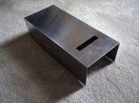
Thanks a lot for the tips! I will build a metal case for the amp and re-do the wires. In fact, encouraged by this first project, I have ordered a LM3875 kit from audiosector.com . I will implement the lessons learnt there. I have already ordered a second toroid to make the next one dual mono and in a more decent metal box.
Best regards
Michael
So don't make antennas by leaving enclosed loop area.
Hi Tom,
This is very interesting!!!
Could you pleas further explain this to us. This is the first time I hear about it.
RGDS
Pemo
I would also recommend following all of Tom's guidelines. The fact that there is some noise when the BrianGT is near the computer indicates I could do better. A commercial Hefler amp in the same location is silent. I made a thin aluminum cover but that doesn't do the trick. I just ure the BGT in a different system in another room.
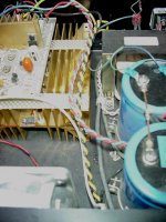
In the previous picture you can see there is no twist between the PS and the amp. Even as short as they are there may well be an antenna effect going on there.
In the previous picture you can see there is no twist between the PS and the amp. Even as short as they are there may well be an antenna effect going on there.
Attachments
Here are some links about Grounding and Shielding Audio Devices.
I approve these links.
http://campuspa.com/downloads/grounding_tutorial.pdf
Grounding and Shielding Audio Devices
Ground noise - Wikipedia, the free encyclopedia
Faraday's law of induction - Wikipedia, the free encyclopedia
Star Grounding
What do Twisted Sister and Fruit Loops have in common?
When in doubt twist everything.
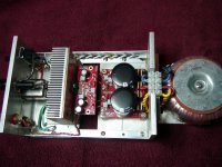
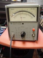
I measured 430 uV RMS at the output of this amp. The HP 3400A true RMS voltmeter, 10 Hz to 10 MHz and a crest factor of 10.
The DC power supply wires are twisted; the 120 AC wires are twisted and shielded. The wires form the bridge to the caps were not twisted, but it’s a good idea to twist them also. The RCA jacks are isolated form the chassis and are connected to the amp with shielded cable. The AC switch fuse and transformer input connections are in the same small area.
An amplifier input noise can be measured with a test setup using a gain of 1,000, the reading is divided by 1,000 to get the amplifier input noise. Using my Opamp test fixture, I measured a LM3875 input noise of 1.4 uV RMS. In audio power amplifier data sheets, such as LM3874, the amplifier has a gain of 20. Therefore, the amplifier noise will be 20 x 1.4 uV or 28 uV RMS. Any additional signal at the output of the amplifier is a result of noise or him induced by the wiring and/or layout.
http://www.diyaudio.com/forums/anal...screte-opamp-test-circuits-2.html#post3188090
Attachments
- Status
- This old topic is closed. If you want to reopen this topic, contact a moderator using the "Report Post" button.
- Home
- Amplifiers
- Chip Amps
- LM3886 DC offset and hum