Hi. Im building a stereo preamplifier based on OPA2134 .
I would like to know whats the influence of feedback resistor value R19,R18 on sound.
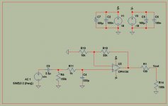
On the schematic i chose them to be typical 10k and 33k. If i choose them to be 1k and 3.3k by keeping the same ratio,how the sound would be affected?
I would like to know whats the influence of feedback resistor value R19,R18 on sound.
On the schematic i chose them to be typical 10k and 33k. If i choose them to be 1k and 3.3k by keeping the same ratio,how the sound would be affected?
Attachments
Maona,
If the circuit is a competent design, the physical layout is done well, and components used are from known and reliable vendors, none of the parts should affect the "sound" of the circuit (I do not use expensive "boutique" parts and never will.)
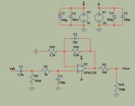
Using lower values in the feedback network will lower the noise, but using high "R" values at the non-inverting input and low "R" values at the inverting input can cause excessive offset voltage at the output. Either the output should be AC coupled, or feedback network should be reconfigured for equal resistance at both of the opamp inputs and AC coupled. The 150k at the non-inverting input is too high. If you change that to something like 50k it will lower noise and maybe even get the offset voltage under control while still giving an input fc under 2Hz.
And I hope you aren't planning to actually use +/- 18 volts to power that chip, life expectancy would be short.
Mike
If the circuit is a competent design, the physical layout is done well, and components used are from known and reliable vendors, none of the parts should affect the "sound" of the circuit (I do not use expensive "boutique" parts and never will.)
Using lower values in the feedback network will lower the noise, but using high "R" values at the non-inverting input and low "R" values at the inverting input can cause excessive offset voltage at the output. Either the output should be AC coupled, or feedback network should be reconfigured for equal resistance at both of the opamp inputs and AC coupled. The 150k at the non-inverting input is too high. If you change that to something like 50k it will lower noise and maybe even get the offset voltage under control while still giving an input fc under 2Hz.
And I hope you aren't planning to actually use +/- 18 volts to power that chip, life expectancy would be short.
Mike
The 150k to ground on the non-inverting input is shunted by the source impedance; since this is drawn as a voltage generator, it's not possible to say what the Johnson noise will be or what the impedance seen by this input is. Typically, however, the reduction in noise figure of the stage due to lowering the feedback loop resistance in an arrangement like this by a factor of 10 will be ~1dB and you could reduce the values to 150R/450R since the load is 100k and the OPA134 will drive 600R. It's necessary to perform a more accurate calculation or do measurements to reliably establish the exact numbers.
This will be insignificant (inaudible) in the majority of cases, but a couple of dB lower noise figure can be significant in some circumstances. This is an impact on noise (hiss), other aspects of the sound will be unaffected to all intents and purposes.
This will be insignificant (inaudible) in the majority of cases, but a couple of dB lower noise figure can be significant in some circumstances. This is an impact on noise (hiss), other aspects of the sound will be unaffected to all intents and purposes.
Last edited:
.............And I hope you aren't planning to actually use +/- 18 volts to power that chip, life expectancy would be short.
Mike
That's within the recommended range
")
----------------------------------------------------------------------------------------------------
DC offset is minimal as this is a FET opamp so there are no worries on unbalanced bias "currents".
Also if you are really interested in sound quality and tweaks then have a read at this thread and in particular some of the links I post too,
http://www.diyaudio.com/forums/analog-line-level/196461-different-opamp-compensation-technique.html
http://www.diyaudio.com/forums/analog-line-level/196461-different-opamp-compensation-technique.html
Mooly,
So you recommend running components right up to thier maximum ratings? I feel much better leaving some safety margin.
Mike
I would be happy at the 18 volt limit for these opamps providing the PSU was well behaved. They are designed to work at that voltage 24/7. Its not like running a transistor at max Vce where other factors come into play.
To quote from the data sheet,
"OPA134 op amps are easy to use and free from phase
inversion and overload problems often found in common
FET-input op amps. They can be operated from
±2.5V to ±18V power supplies."
I forgot to say that i will use OPA2134 for stereo version and a gain of about 9dB.
The inpul filter (R1,C1,R2,C2) is to prevent RF from entering but in some designs on the net i have seen that they dont use one at all and omit R2,C2. necessary ?
As far as the compensation capacitor C3 and the bandwith of the opamp what do you suggest?
The inpul filter (R1,C1,R2,C2) is to prevent RF from entering but in some designs on the net i have seen that they dont use one at all and omit R2,C2. necessary ?
As far as the compensation capacitor C3 and the bandwith of the opamp what do you suggest?
Attachments
Unless you have a problem with RF (live near a transmitter etc) then I would omit the input filter. 22pf looks OK but what I would advise is that you determine the best value by observing squarewave response on a scope. This is an old thread but shows what you should be looking at. In practice layout and stray capacitcance means the optimum value often has to be determined in situ,
Post #1096
http://www.diyaudio.com/forums/chip...g-audio-integrated-opamps-55.html#post2018832
Post # 1106
http://www.diyaudio.com/forums/chip...g-audio-integrated-opamps-56.html#post2019009
Post #1096
http://www.diyaudio.com/forums/chip...g-audio-integrated-opamps-55.html#post2018832
Post # 1106
http://www.diyaudio.com/forums/chip...g-audio-integrated-opamps-56.html#post2019009
The problem is that i dont have a scope.Just simulation results from LT Spice which is just an approximation to reality but not reality.
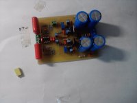
Here's a picture of my pcb with some parts missing.What capacitor should i choose for the input? I have these orange MKT and the smaller yellow ones.I read that these big sized capacitors can act as 'microphones' sometimes.Space is provided for both types of these capacitors.
Here's a picture of my pcb with some parts missing.What capacitor should i choose for the input? I have these orange MKT and the smaller yellow ones.I read that these big sized capacitors can act as 'microphones' sometimes.Space is provided for both types of these capacitors.
Attachments
Last edited:
Hi
Here are some links to previous projects using OPA2134 as a pre :
http://www.diyaudio.com/forums/chip-amps/122639-soap-mkiii-simple-opamp-pre-onboard-psu.html
http://www.diyaudio.com/forums/chip-amps/160469-soap-evolution-simple-opamp-pre.html
Phil
Here are some links to previous projects using OPA2134 as a pre :
http://www.diyaudio.com/forums/chip-amps/122639-soap-mkiii-simple-opamp-pre-onboard-psu.html
http://www.diyaudio.com/forums/chip-amps/160469-soap-evolution-simple-opamp-pre.html
Phil
With 150K input impedance either is fine as regards low frequency cut-off. Sound quality wise I'm probably not the right person to ask as I'm a non-believer
I would choose on technical merit probably going for the physically smaller cap as it has a smaller footprint and area to minimise noise pickup.
I would choose on technical merit probably going for the physically smaller cap as it has a smaller footprint and area to minimise noise pickup.
I am of the opposite opinion.Unless you have a problem with RF (live near a transmitter etc) then I would omit the input filter. .............
I prefer to see an RF filter at the input of every receiver.
I generally set the source equipment input filters to ~ twice the frequency of the Power Amp RF filter, i.e. for my PA I use ~680ns and for Sources I use ~330ns. That extra octave takes very little off the required audio signal, but does give extra and useful attenuation of RF.
Modern homes are full of RF transmitters.
- Status
- This old topic is closed. If you want to reopen this topic, contact a moderator using the "Report Post" button.
- Home
- Amplifiers
- Chip Amps
- OPA2134 Preamplifier