If you gonna do p-to-p I might suggest start from Mick Feuerbacher project as it is, use 100W light bulb in series with your trafo primary. Use some cheap speaker to test your new amp.
Once it's working you can go further with schematic improvements, speaker protection addendum. I would not recommend dealing with more complicated schematics than Mick's one without PCB.
I wanted to use my computer as input source, I am not sure about the presence or absence of DC, So should I go with Mick Feuerbacher's Three-resistor LM3886 chip amp?
AndrewT,
I was actually referring to your post #8 where you elaborated on everything else but didn't reiterate the need for a lower fc for the feedback network. The OP may not be experienced enough to understand the 2nd schematic suffered the same shortcoming, sometlmes repetiton is necessary for the sake of clarity, and I don't see anything in the forum rules agianst repeating oneself.
I agree totally with you on the Cf/Rf issue. If the circuit layout is properly done, and gain is set reasonably high, say 26dB (X20) or more they shouldn't be needed. But leaving space to add later is sound advice (no pun intended.)")
Gohar,
I just saw your latest posts, and no, DO NOT build that amp (the "Mick Feuerbacher"), it is totally lacking the necessary components to have a stable, useable amp, and using the DC blocking cap at the input will solve any possible DC input offset issues before they happen (see guidlines below.)
I don't know how much experience you have, but if you follow AndrewT's advice, you won't go wrong (especially on issues of safety)
Here's a set of general guide lines I recommend;
1) Keep lead length and circuit layout reasonably compact, but don't crowd together so tightly that you can't change something later. Keep power supply bypass caps as close as possible to their respective chip-amp pins.
2) There should be three separate grounds from the amp to the power supply "0 volts" (ground); one for the low level input side, one for the on board power supply bypass caps and one for the speaker output.
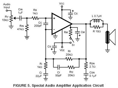
3) Use all of the components that are sometimes refered to as "optional", they are not if you want an amp that will be stable and operating properly. This includes the input filter to block RF, AC coupling on both input and feedback network with correctly configured high-pass roll offs, power supply bypass with a large electrolytic (470 uF or more) and a small (10 nF to 100 nF) COG or NPO ceramic disc connected directly on the chip amp pins (or as close as possible, I usually put those on the underside of the board to acomplish that), and the output "Zobel" network and inductor.
4) These chips are designed to run a MINIMUM gain of X10 (+20 dB) for stability, in my experience, less than about X15 (23.5 dB) is probably as low as one should go to stay away from the stability margins, and above X40 (32 dB) starts to get into noise amplification territory.
Doing it this way (especially for inexperienced builders) will almost guarantee a good result.
Mike
I was actually referring to your post #8 where you elaborated on everything else but didn't reiterate the need for a lower fc for the feedback network. The OP may not be experienced enough to understand the 2nd schematic suffered the same shortcoming, sometlmes repetiton is necessary for the sake of clarity, and I don't see anything in the forum rules agianst repeating oneself.
I agree totally with you on the Cf/Rf issue. If the circuit layout is properly done, and gain is set reasonably high, say 26dB (X20) or more they shouldn't be needed. But leaving space to add later is sound advice (no pun intended.)
Gohar,
I just saw your latest posts, and no, DO NOT build that amp (the "Mick Feuerbacher"), it is totally lacking the necessary components to have a stable, useable amp, and using the DC blocking cap at the input will solve any possible DC input offset issues before they happen (see guidlines below.)
I don't know how much experience you have, but if you follow AndrewT's advice, you won't go wrong (especially on issues of safety)
Here's a set of general guide lines I recommend;
1) Keep lead length and circuit layout reasonably compact, but don't crowd together so tightly that you can't change something later. Keep power supply bypass caps as close as possible to their respective chip-amp pins.
2) There should be three separate grounds from the amp to the power supply "0 volts" (ground); one for the low level input side, one for the on board power supply bypass caps and one for the speaker output.
3) Use all of the components that are sometimes refered to as "optional", they are not if you want an amp that will be stable and operating properly. This includes the input filter to block RF, AC coupling on both input and feedback network with correctly configured high-pass roll offs, power supply bypass with a large electrolytic (470 uF or more) and a small (10 nF to 100 nF) COG or NPO ceramic disc connected directly on the chip amp pins (or as close as possible, I usually put those on the underside of the board to acomplish that), and the output "Zobel" network and inductor.
4) These chips are designed to run a MINIMUM gain of X10 (+20 dB) for stability, in my experience, less than about X15 (23.5 dB) is probably as low as one should go to stay away from the stability margins, and above X40 (32 dB) starts to get into noise amplification territory.
Doing it this way (especially for inexperienced builders) will almost guarantee a good result.
Mike
Michael Bean,
I've planned to use this PSU
I've built this PSU but as you said that
should i connect them on chip pins? instead of in PSU?
What about this chip-amp?
Mick Feuerbacher Audio Projects
i am confused to select which circuit,
another is http://www.diyaudio.com/forums/blogs/wintermute/134-construction-p2p-lm3886-gainclone-part-1.html
All of You are very helpful.
Regards.
I've planned to use this PSU
An externally hosted image should be here but it was not working when we last tested it.
I've built this PSU but as you said that
,and a small (10 nF to 100 nF) COG or NPO ceramic disc connected directly on the chip amp pins
should i connect them on chip pins? instead of in PSU?
What about this chip-amp?
Mick Feuerbacher Audio Projects
i am confused to select which circuit,
another is http://www.diyaudio.com/forums/blogs/wintermute/134-construction-p2p-lm3886-gainclone-part-1.html
All of You are very helpful.
Regards.
gohar,
Agian, don't build that "Mick Feuerbacher" thing, the kindest comment I can make about it is it's incomplete and most likely prone to all sorts of problems.
The schematic in post #25 is OK if you apply the general guidelines I, AndrewT and others have posted
And yes, that power supply will work fine.
As for supply bypassing;
On the power supply itself, most people use bypass film type caps that are far too small to do any real good, usually something like 10nf to 1uf across the large electrolytics just "because that's how it's done." A good quality 4.7uf to 10uf film cap will work well here. It will reduce the electro-caps inductive component and lower power supply output impedance at high frequencies.
For the chip amp, you should put COG or NPO type of disc caps, something like 10nf to 100nf, directly from both chip amp power supply pins to power ground, and also electro-caps (470uf or more) to power ground as physically close as possible to the chip amp, and remember to watch the actual working voltages and leave some extra margin for up to +/- 20% mains variation to be safe.
I also strongly urge you to use a "light bulb tester" when doing the initial testing for peace of mind, you can search this forum for more info on that.
Mike
Last edited:
Thanks for the clarity at the expense of succinctness.All the Power Grounds are connected together.
All the Signal Grounds are connected together.
To a noob like me, speaker cabling carries signal but one could also say it carries power.
Post 8 was extraordinarily helpful, and it not mentioning the speaker ground explicitly led me to resurrect the thread. I might assume speaker ground comes under the mentioned "main audio ground", which seems neither signal nor power, hence the unhelpfulness and incompleteness of your post #29.Not obtuse.
The Signal Grounds are listed in post8.
Audio San drew that description up and posted it in 16.
But, maybe it's you that allege my posts are unhelpful.
Is this another you want to add to that unhelpful list?
Is my assumption correct? Or is it in fact power ground, or some other ground not yet mentioned?
If you are building a monoblock then all except the Signal Ground get connected together.
You can call this the Main Audio Ground (MAG), (my preferred term).
Others may call it the Power Ground.
When building a two, or more, channel amplifier then the grounding ballgame changes.
The Power Ground must be on the amplifier. The Main Audio Ground is likely to be elsewhere. I recommend that the Speaker Return must follow the speaker output lead and traces to eventually reach the MAG.
- Status
- This old topic is closed. If you want to reopen this topic, contact a moderator using the "Report Post" button.
- Home
- Amplifiers
- Chip Amps
- Lm3886