In this schematic,

if i changed Rf to 20k, what were the changes produced? As i can't able to find 22k for Rf so i decided to go with 20k for Rf. and what about the schematic? is it fully functional with original component values?
I am going to place 50k pot for Rin instead of 25k. what changes does it make?
And if i eliminate the pot then?
I am planning to do it Point to Point.
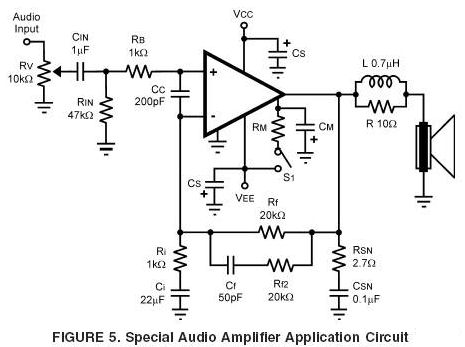
Yes you can use Rf=20K instead of 22K just recalculate the gain (Rf/Ri) or adjust Ri accordingly. As I recall LM3886 should better be not used with gain below 10 i would say 20 is a ball park.
Check DC decoupling capacitor remark from AndrewT it is safe to have one implemented. ELNA Silmic Nichicon Muse are good stuff. Foil-paper-oil (like Jensen) are better but good electrolytic should do the job and foil would be overkill for the job.
Rg might be from 600Ohm up to 1MOhm so 20k is OK value too.
post5 shows the complete implementation.
BUT !!!!!
there is a standard convention used in allmost all schematics.
All the Ground connections are shown as having the same symbol !!!!!
The Signal Ground must not be connected to the Power Ground.
Instead:
Connect bottom of Ci directly to bottom of Rin.
Connect bottom of Rin directly to Bottom of Rv (vol pot).
Connect bottom of Rv directly to Barrel of RCA input socket.
This group of 4 connection are the Signal Ground.
One more:
Connect the Signal Ground to the Main Audio Ground using a low value resistor. 10r is usually adopted. Any value from 1r0 to 100r will probably work. You can even use 0r0 when you build a monoblock.
There is another problem left over.
If you connect other mains powered equipment to the input RCA, AND there is a mains fault in that other equipment AND that other equipment does not have a functional PE, then the mains fault can burn out the resistor and leave the input side of the amplifier and the connected equipment with a LIVE voltage that is exposed to touch.
Use a pair of inverse parallel diodes (1n4002) across the resistor. These diodes will pass sufficient current to the power amp PE and will blow the fuse in the connected equipment even when there is no functional PE in that faulty equipment. But all fuses must be close rated. Never stick in big fuses to stop them blowing when you switch ON
These diodes are a potential life saver. Do not omit them, if you have some "double insulated" audio/visual equipment.
Now some advice, you decide if you want to follow or not.
I don't like the Cc across the +IN & -IN pins. I prefer to have the bottom of Cc directly connected to the botom of Rin, i.e. to Signal Ground.
To augment the RF attenuation, I like to add second stage by inserting a 47pF directly across the input RCA, from Hot to Barrel.
I connect the bottom of +ve (top) Cs directly to the bottom of the -ve (lower) Cs with a very short wire or trace.
I then connect the bottom of Csn (the output Zobel) directly to the Cs common ground (decoupling ground).
I recommend that at least initially you omit Cf & Rf2. You can leave space on your PCB to add them later if testing shows they are required to aid stability.
Last edited:
What should be the value of DC blocking capacitor?
I can highly recommend: ELNA SILMIC II 2.2uF 50v
Well here is good film one B32560J475K - EPCOS - CAPACITOR, 4.7UF, 63V | Farnell United Kingdom
Yes its good point.The Signal Ground must not be connected to the Power Ground
And which schematic should I follow?
This one?
Or this one?
I have planned to go with Point to Point or "Bug style" construction, no PCB or other boards.
post5 shows the complete implementation.
read !And which schematic should I follow?
AndrewT,
I'm kinda surprized (and maybe even a little disappointed!) that you didn't catch the problem with the input and feedback network time constants on the second schematic. Fc at input is lower than feedback Fc, clearly a less than optimal implementation.
Mike
I'm kinda surprized (and maybe even a little disappointed!) that you didn't catch the problem with the input and feedback network time constants on the second schematic. Fc at input is lower than feedback Fc, clearly a less than optimal implementation.
Mike
Last edited:
post5 shows the complete implementation.
BUT !!!!!
there is a standard convention used in allmost all schematics.
All the Ground connections are shown as having the same symbol !!!!!
The Signal Ground must not be connected to the Power Ground.
Instead:
Connect bottom of Ci directly to bottom of Rin.
Connect bottom of Rin directly to Bottom of Rv (vol pot).
Connect bottom of Rv directly to Barrel of RCA input socket.
This group of 4 connection are the Signal Ground.
One more:
Connect the Signal Ground to the Main Audio Ground using a low value resistor. 10r is usually adopted. Any value from 1r0 to 100r will probably work. You can even use 0r0 when you build a monoblock.
like this?
Attachments
AudioSan,
That looks good, except for the issue I mentioned in my last post. The input fc is about 3.4Hz and the feedback fc is about 7.2Hz which allows the possibility that the amp may be asked to pass a signal that the feedback network can't control. I recommend at least 100uf (or more) for Ci, that will lower feedback fc to about 1.6Hz (or less) which is much better.
Mike
")
BTW, I am new to Electronics and Audio. But I am interested in these.
If you gonna do p-to-p I might suggest start from Mick Feuerbacher project as it is, use 100W light bulb in series with your trafo primary. Use some cheap speaker to test your new amp.
Once it's working you can go further with schematic improvements, speaker protection addendum. I would not recommend dealing with more complicated schematics than Mick's one without PCB.
I'm kinda surprised and even disappointed that you did not read my post3AndrewT,
I'm kinda surprized (and maybe even a little disappointed!) that you didn't catch the problem with the input and feedback network time constants on the second schematic. Fc at input is lower than feedback Fc, clearly a less than optimal implementation.
Mike
which applies universally when the same, or similar, schematic is re-posted. I try not to repeat myself, it's flouting of the Forum Rules to do so.Ci restricts the bass output.
Expect the bass to roll off from about 10Hz. I would use 220uF, or maybe 150uF
- Status
- This old topic is closed. If you want to reopen this topic, contact a moderator using the "Report Post" button.
- Home
- Amplifiers
- Chip Amps
- Lm3886