My Gainclone is 90% finished now ")
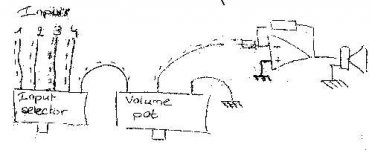
I build this amp as an "integrated" amp and not a power amp: there are multiple inputs (4), an input selector and a volume pot
The only thing I still don't know how to do, is the grounding of the inputs.
All the inputs use a shielded cable, and that causes me some trouble...
The inputs go to the rotatory selector switch, then, the output of this one goes to the volume pot, and the output of the pot goes to the input resistance of the chip.
Now: where do I connect the shields?
Edit: the dotted lines on the (poor) drawing represents the shield
Attachments
Hi Bricolo,
From the bottom of my inexperience I'll try to share my doubts with you...
I think there are two possible situations. Keep in mind that the cables coming from the sources to your amp have almost certainly the grounds connected together at the origin.
1. If the amp is truly dual-mono (two separate PS, two separate ground stars), I second Nuuk's opinion that the best way would be to keep the grounds separate and to use a 2Pole-4Toggle switch in order to switching both signal and grounds.
This should be beneficial for avoid large-scale ground loops among different source components. Otherwise, one could connect the input grounds with the shortest possible wire and use a 1Pole-4Toggle switch. Again, no ground loops inside the amp.
2. If the amp is not dual mono (your configuration), I suspect you can only choose how big to make the ground loop: if you keep the input grounds separate, the loop will start at the source and end at the center of the (global) ground star. If you instead connect the grounds of the input jacks you'll make a smaller loop, from the jacks to the (global) ground star. Maybe this solution is less bad. Another thing you could do is to switch both signal and ground, but connecting the left and right input grounds right after switch. Once connected the grounds, you could use a single wire to bring the input ground to the amp; so no loop, but a weird return path for one channel.
Hope the great people of this forum will help clarifying the best way to do the job.
Ciao, Massimo
Off topic, balanced lines
Antomas,
You have just clarified one of the benefits of using balanced connections (the others being CMR and a somewhat universal set of specifications for impedance and voltage) on the better quality studio and pro-sound gear. I had never thought of it in those terms before. You always hear about common mode rejection and long cable runs when people explain the theory, but I have never heard a factory rep point to ground loop issues between equipment. Now I think those that are mixing balanced and unbalanced gear (I was in my rig) are very lucky if they don't encounter any ground loop problems. I went to great lengths to make sure the AC lines/grounds were starred from the distro panel, but was at the mercy of the manufacturer when dealing with outboard gear, like EQs, reverbs and compressors. I was one of the lucky ones that didn't have many grounding issues. Now those blasted cheap dimmer racks throwing junk all over the AC lines were another story!!
Thanks for your explaination,
Tom
Hi Tom,
Ehm... I really didn't think about balanced connections... or, at least, this wasn't my intention...
What I tried to describe (to "explain" seems a bit too strong to me) was my idea about potential ground loops involving a non-dual-mono amp. Apparently, very few people are afraid of that, so maybe the problem is not so terrible.
Sorry about the misleading message. (Btw, the english wasn't very good as well.)
Ciao, Massimo
Ehm... I really didn't think about balanced connections...
or, at least, this wasn't my intention... What I tried to describe (to "explain" seems a bit too strong to me) was my idea about potential ground loops involving a non-dual-mono amp. Apparently, very few people are afraid of that, so maybe the problem is not so terrible.
Sorry about the misleading message. (Btw, the english wasn't very good as well.)
Ciao, Massimo
Hi antomas,
Sorry if I got off on a tangent...that's just the way my brain works! Yes, not the same topic really, but maybe this is one area where a balanced configuration solves a problem, even with regard to a single power supply amp. Too bad it would add more components, and in the case of quality input transfomers, fairly expensive ones. Not very practical for most of us.
I guess you just had me thinking about a preamp schematic I had run across, where, even though it was single ended as far as the active circuit was concerned, there were some pretty expensive transformers on every input prior to the selector switch. At the time I thought it was complete overkill and possibly a waste of money, space, and effort. Your post just shed some light on why the designer went to such lengths to keep everything balanced, and the grounds isolated.
Thanks,
Tom
BTW, I think your English is fine!
Sorry if I got off on a tangent...that's just the way my brain works!
Yes, not the same topic really, but maybe this is one area where a balanced configuration solves a problem, even with regard to a single power supply amp. Too bad it would add more components, and in the case of quality input transfomers, fairly expensive ones. Not very practical for most of us.I guess you just had me thinking about a preamp schematic I had run across, where, even though it was single ended as far as the active circuit was concerned, there were some pretty expensive transformers on every input prior to the selector switch. At the time I thought it was complete overkill and possibly a waste of money, space, and effort. Your post just shed some light on why the designer went to such lengths to keep everything balanced, and the grounds isolated.
Thanks,
Tom
BTW, I think your English is fine!
- Status
- This old topic is closed. If you want to reopen this topic, contact a moderator using the "Report Post" button.
- Home
- Amplifiers
- Chip Amps
- Grounding dilema