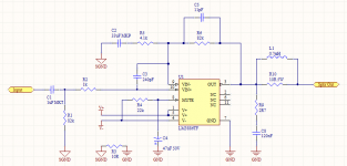
A variation that provides filtering for DC & ultrasonic/RF frequencies but doesn't use any electrolytic capacitors in the signal path. Should be a good compromise between signal quality and industrial robustness (though the gain is quite low - inevitable given sane component value restraints).
2nd chip amp project. Haven't built it yet.
Any thoughts welcome.
2nd chip amp project. Haven't built it yet.
Any thoughts welcome.
Attachments
but doesn't use any electrolytic capacitors in the signal path.
What do you mean? C1 (obviously), C2, C3 even C8 (zobel) are in signal path...? EDIT: Oh, I see. Electrolytics. So 33uF MKP for feedback.
Should be a good compromise between signal quality and industrial robustness (though the gain is quite low - inevitable given sane component value restraints).
There was similar thread few days ago asking to compare Apex 3886 and the datasheet 3886. Why not choose any of them?
though the gain is quite low
The gain is approximately 82K/4k1=20x (not talking about the top freq), similar with the datasheet (20K/1K=20x if I'm not mistaken). The minimum is around 12x (so 12K/1K is possible with extra care with layout etc).
Tweaking with basic topology like this, there are points that I've learnt:
1) With equivalent capacitor compensation, the lower the gain the better the sound. Thus you have to make sure that everything (layout mainly) is good so that lower gain doesn't create instability (oscillation). You have to have tools to monitor this instability so you can use as low gain as possible.
2) In any amplifier circuit, the series resistor at input will affect THD. Because we cannot trust the accuracy of simulation, then tweaking by ears is still possible. In many opamps or even gainclone, I choose smaller resistance, not 1K. Type of this resistor is also audible. My taste is with carbon (Allen Bradley is cheap but never use this in feedback)
3) I have an hypothesis about phase issue and feedback. That is after building and listening (tweaking precisely) that lead me to CFB preference. I prefer (observation by tweaking by ears) smaller feedback resistor. The datasheet uses 20K. I can predict that 82K will sound worse (you need this big value so you can use smaller 33uF so you can use MKP). If you can go with 20K why 82K? 33uF MKP is expensive.
Last edited:
Then you go and ruin it with C4.
Ahem. Really? An electrolytic on a logical input is going to "ruin it"?
the title pronounces
LM3886 variation - filtered without el caps
") In the title I said "filtered without electrolytic capacitors" : it would be in error to construe I meant the whole circuit was without them. I hope that clarifies the semantic aspect of this thread.
In the title I said "filtered without electrolytic capacitors" : it would be in error to construe I meant the whole circuit was without them. I hope that clarifies the semantic aspect of this thread. Not a very interesting thread, I know. There are a few designs that do DC without electrolytics but none I can see that filter both DC and RFI. Besides, I'm open to people more experienced than I (most people on this forum) making suggestions and/or correcting my calculations before I start soldering. As noted, it's a little more expensive to make with film capacitors, especially using reputable brands (not about to wade into the "capacitor brand = placebo" debate).
The two most common set-ups for the 3886 (etc) chip amps either omit bandpass filtering (the classic gainclone) or have a bipolar electro on the feedback because, at reference gain, the RC filter there needs to have a very high value cap. Dropping feedback drops the required anti-DC RC feedback capacitance to a level suitable for film capacitors.
The main reason for this attempt, trivial as it may be, is to remove the aforementioned bipolar electro from the circuit. Best practice in any circuit is to minimise the number of electrolytics as much as possible for reason of long term reliability. I'm sure I read an article ages ago by Rod Elliot (ESP) claiming bipolar electros significantly change capacitance over time. Of course, the bare minimum gainclone design requires almost no capacitors at all, but it is vulnerable to DC offset and RFI. Swings and roundabouts, as the saying goes.
I'm going to have to recheck all my calculations. I chose 82K because a high pass filter on the feedback (matching impedance with the input?) requires either a large resistor or a large capacitor and I've already got some 33uF 100V film caps in my parts collection.<snip>
3) I have an hypothesis about phase issue and feedback. That is after building and listening (tweaking precisely) that lead me to CFB preference. I prefer (observation by tweaking by ears) smaller feedback resistor. The datasheet uses 20K. I can predict that 82K will sound worse (you need this big value so you can use smaller 33uF so you can use MKP). If you can go with 20K why 82K? 33uF MKP is expensive.
Thanks for the useful feedback (no pun intended).
That means that the amplifier circuit has non-linear input impedance - which can happen. However, if the input series resistor has to be small to avoid distortion then this means that the source impedance from which the signal comes must be even lower. If the chip is this sensitive to source impedance it really ought to have a buffer in front of it.Jay said:In any amplifier circuit, the series resistor at input will affect THD.
Smaller feedback resistors (other things being equal) will mean less HF boost due to stray capacitance at the feedback pin, but can also cause greater distortion due to thermal effects if the feedback resistor has highish tempco or too small power rating. A balance needs to be struck. This sort of thing can't be done by ear, as ears are very easily fooled. Much better to be done by datasheet, calculator and measurements; unless you are building an amp with built-in fixed tone controls and FX.Jay said:I prefer (observation by tweaking by ears) smaller feedback resistor.
Finally, note that physically large caps can inject more hum and RF into sensitive circuit nodes so better screening may be needed than is necessary with the more usual electrolytics.
That means that the amplifier circuit has non-linear input impedance - which can happen. However, if the input series resistor has to be small to avoid distortion then this means that the source impedance from which the signal comes must be even lower. If the chip is this sensitive to source impedance it really ought to have a buffer in front of it.
Of course they need it. Which one does not? It is all about how much is audible or not.
Smaller feedback resistors (other things being equal) will mean less HF boost due to stray capacitance at the feedback pin, but can also cause greater distortion due to thermal effects if the feedback resistor has highish tempco or too small power rating.
Finally, note that physically large caps can inject more hum and RF into sensitive circuit nodes so better screening may be needed than is necessary with the more usual electrolytics.
The TSSA is a good example to get the feel to work with those issues.
This sort of thing can't be done by ear, as ears are very easily fooled. Much better to be done by datasheet, calculator and measurements.
Measurement, okay. Datasheet, calculator/simulator? Those are full of assumed numbers. Some ears can be better.
If you want to do away with electrolytics in the signal path, why not just use a servo?
Few days ago Mikelm posted, I think in the "Simple Symmetrical Amplifier" thread, saying that a (especially when badly designed) servo may increase the level of very high order harmonics. I have never simulated such thing as I have had big doubt with servo but couldn't find a reason (as I don't want to use it).
High order harmonics always have relationship with fatigue. Caps in feedback may color the sound, blur the sound, or whatever, but it doesn't create offending sound. So there is nothing too wrong with using caps. It can be a better option.
The small-signal path might be free of electrolytics. But THAT signal path stops, right after the chipamp input pins.
The real signal path, the one that directly provides the exact signal that makes the sound come out of the speakers, is the power supply.
Virtually ALL of the current that IS the actual signal that you HEAR, comes not past, but directly OUT of, the electrolytic capacitors in the power supply, or out of the ones that decouple the chipamp's power supply inputs.
Get over it. (Then embrace it. Read on.)
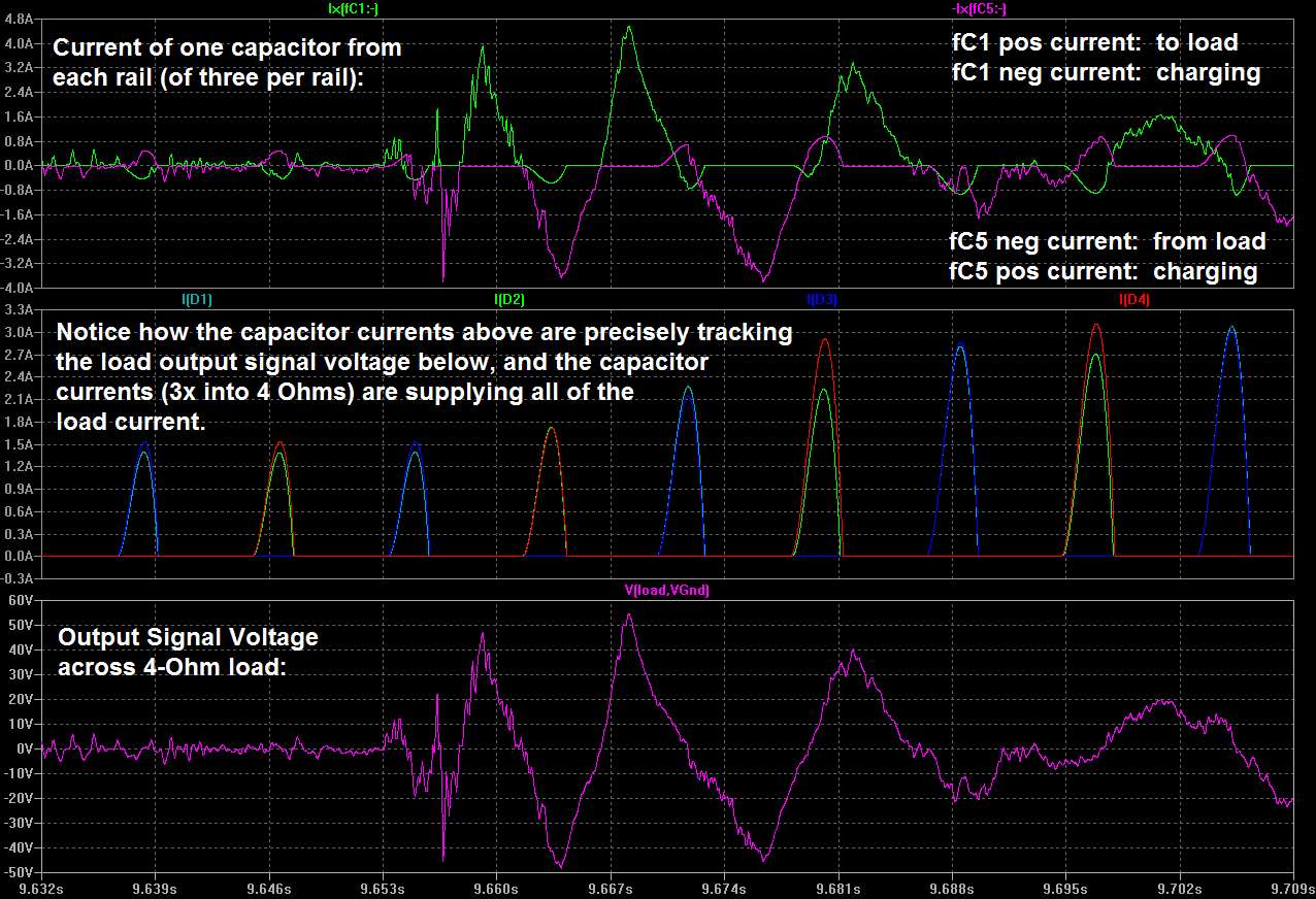
In case you still have doubts about all of the load current coming straight out of the electrolytic caps, here is some pretty good proof:
http://www.diyaudio.com/forums/atta...3-power-supply-resevoir-size-zoom3a_33kuf.jpg
Which is part of my post #372 at:
http://www.diyaudio.com/forums/power-supplies/216409-power-supply-resevoir-size-38.html#post3117390
Since that is the case, the best thing to do is to optimize the parasitic inductance and resistance between the reservoir caps and the chip's power pins, and between the decoupling caps and the chip's power pins, which in this case means minimizing those parasitics. (It's not too difficult. Read on.)
According to Terry Givens, a noted expert in the power supply field, one excellent way to do that would be to populate a two-sided circuit board with a matrix (rows and columns) of electrolytics, one circuit board per power rail, with one side of each board being that rail's ground and the other side being that rail's voltage. Leave all of the copper on both sides, removing just enough to insulate around a hole for one lead of each cap to go to the other side of the board. Bend about a half-inch of each lead and solder most of its length to the surface of the board.
For important details about that, see his posts about it, starting at post # 1009, at the link below and reading the rest of his posts up through at least post # 1024.
http://www.diyaudio.com/forums/power-supplies/216409-power-supply-resevoir-size-101.html#post3154192
If, for some reason, you had to do it with point-to-point wiring, and no PCB, you could try the approach in post # 1004, there.
For the best-possible transient response, I believe that you will still need to also have several (as many as will fit, totaling at least 200-300 uF, but 10x that would be better) small electrolytic decoupling caps right AT each power pin of the chipamp, in parallel with each other, with their other leads taking separate short-as-possible paths to the speaker and zobel ground point, which should also be located as close as possible. (It's very important that those caps provide the shortest-possible round-trip path, and that there are as many in parallel as possible, all with separated leads/conductors in parallel that stay separated all the way to the decoupling points, if at all possible.) Film caps are not easy to recommend, there. You might get away with it but without some serious test equipment (network analyzer and spectrum analyzer and a good oscilloscope) and calculations, and a degree in electrical engineering plus relevant experience, there's too much risk of creating a resonant LC tank that will ring and/or oscillate at very high frequencies, seriously degrading performance or even destroying the chip. ALSO, you "must" have a small X7R-type ceramic BYPASS cap in parallel, there, too, for high-frequency stability. Again, using a "better quality" C0G or NPO type there, or a film cap, is probably too risky. (But, you can certainly experiment with it and might get lucky.)
Cheers,
Tom
The real signal path, the one that directly provides the exact signal that makes the sound come out of the speakers, is the power supply.
Virtually ALL of the current that IS the actual signal that you HEAR, comes not past, but directly OUT of, the electrolytic capacitors in the power supply, or out of the ones that decouple the chipamp's power supply inputs.
Get over it. (Then embrace it. Read on.)
In case you still have doubts about all of the load current coming straight out of the electrolytic caps, here is some pretty good proof:
http://www.diyaudio.com/forums/atta...3-power-supply-resevoir-size-zoom3a_33kuf.jpg
Which is part of my post #372 at:
http://www.diyaudio.com/forums/power-supplies/216409-power-supply-resevoir-size-38.html#post3117390
Since that is the case, the best thing to do is to optimize the parasitic inductance and resistance between the reservoir caps and the chip's power pins, and between the decoupling caps and the chip's power pins, which in this case means minimizing those parasitics. (It's not too difficult. Read on.)
According to Terry Givens, a noted expert in the power supply field, one excellent way to do that would be to populate a two-sided circuit board with a matrix (rows and columns) of electrolytics, one circuit board per power rail, with one side of each board being that rail's ground and the other side being that rail's voltage. Leave all of the copper on both sides, removing just enough to insulate around a hole for one lead of each cap to go to the other side of the board. Bend about a half-inch of each lead and solder most of its length to the surface of the board.
For important details about that, see his posts about it, starting at post # 1009, at the link below and reading the rest of his posts up through at least post # 1024.
http://www.diyaudio.com/forums/power-supplies/216409-power-supply-resevoir-size-101.html#post3154192
If, for some reason, you had to do it with point-to-point wiring, and no PCB, you could try the approach in post # 1004, there.
For the best-possible transient response, I believe that you will still need to also have several (as many as will fit, totaling at least 200-300 uF, but 10x that would be better) small electrolytic decoupling caps right AT each power pin of the chipamp, in parallel with each other, with their other leads taking separate short-as-possible paths to the speaker and zobel ground point, which should also be located as close as possible. (It's very important that those caps provide the shortest-possible round-trip path, and that there are as many in parallel as possible, all with separated leads/conductors in parallel that stay separated all the way to the decoupling points, if at all possible.) Film caps are not easy to recommend, there. You might get away with it but without some serious test equipment (network analyzer and spectrum analyzer and a good oscilloscope) and calculations, and a degree in electrical engineering plus relevant experience, there's too much risk of creating a resonant LC tank that will ring and/or oscillate at very high frequencies, seriously degrading performance or even destroying the chip. ALSO, you "must" have a small X7R-type ceramic BYPASS cap in parallel, there, too, for high-frequency stability. Again, using a "better quality" C0G or NPO type there, or a film cap, is probably too risky. (But, you can certainly experiment with it and might get lucky.)
Cheers,
Tom
Last edited:
- Status
- This old topic is closed. If you want to reopen this topic, contact a moderator using the "Report Post" button.
- Home
- Amplifiers
- Chip Amps
- LM3886 variation - filtered without el caps