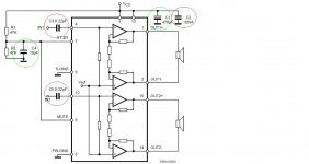
Hello i am a beginner so i would like to tell me if the conversion of the schematic to stripboard is correct.
Under C3 and C5 there are cut tracks.
An externally hosted image should be here but it was not working when we last tested it.
An externally hosted image should be here but it was not working when we last tested it.
Under C3 and C5 there are cut tracks.
Hi priest91. Can't get your pictures to open. Try attaching them directly as here,
Too add a photo,
First click "go advanced" in the box below the "quick reply" message box. Doesn't matter if you decide half way through a message to do that, it carries it foward.
Then click "Manage attachements"
Click browse in the first box at the top and find your picture. Repeat for any more pictures.
Click upload... a message appears "uploading"
When complete, scroll down to the bottom of page and click "close this window"
The pictures should now be attached and when you post will appear. I don't think they show in message preview... they never used to anyway.
Make sure your pics aren't too big, a couple of 100k is plenty, and many object when they are massive and it alters the margins
It tells you in the attachments window what max sizes are allowed.
Hi 91
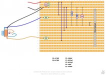
What connections i can see on the stripboard look OK but i cant see any OUT connections .
I have suggestions
make the power ground the closest gound to the negative lead so move c11-k11 to c5-k5 and move the jack socket ground to c7 so the power noise is not going past the signal ground.
Move the positive rail connections from a8-f8 to a19-f19 and a9-p9 to a21-p21 then cut the tracks at f18 and p20 , this will reduce the length of positive rail track that is running next to and in parallel to the input rails and thus reduce power rail noise pickup.
Last edited:
- Status
- This old topic is closed. If you want to reopen this topic, contact a moderator using the "Report Post" button.
- Home
- Amplifiers
- Chip Amps
- TDA7266SA - Schematic to stripboard