Hi,
I want to build a power amp with LM3886 and use LM1036 for tone/volume/balance.
This will be my fist amp and my second project in electronics")
I managed to build them on a test board. I have the input from a MP3 player and I have used a 40W RMS speaker and a pair of headphones for testing.
I have tested the 3886 and it sounds nice, I can't hear any background noise on low volume and/or distortion on max volume of my MP3 player. Also I have tested the 1036 with the headphones and it also sound good. I can't use the max volume cause it's very loud and - on low - I can't hear any noticeable background noise.
The only big problem I get it's a big noise on power ON/OFF from the 1036. With the 3886, I suppose the mute function it's working as expected as I can't hear any ON/OFF noise (when I use it by itself).
Of course, if I link them together (1036 + 3886) I get a big ON/OFF noise in my speaker. Also, there is no way I can max the volume, as it will distort allot.
Do I need to limit the signal level after it gets out of the 1036?
But if I get the signal from the soundcard output from my PC? Should I limit the signal level before it gets feed into the 1036? How do I do this?
Also, I tried to measure the DC offset. With only 3886 it get something like 1mV when on max volume. Conected 1036 + 3886 I measure it to about 40mV (this with the output level on my MP3 player to about 80%, louder than this and I get distortion; I suppose the DC offset it's getting higher too).
I only have a multimeter to do my job.
Any ideea/recomandations?
My electronics skill it's somehow low , so be patient.
Thanks!
I want to build a power amp with LM3886 and use LM1036 for tone/volume/balance.
This will be my fist amp and my second project in electronics
I managed to build them on a test board. I have the input from a MP3 player and I have used a 40W RMS speaker and a pair of headphones for testing.
I have tested the 3886 and it sounds nice, I can't hear any background noise on low volume and/or distortion on max volume of my MP3 player. Also I have tested the 1036 with the headphones and it also sound good. I can't use the max volume cause it's very loud and - on low - I can't hear any noticeable background noise.
The only big problem I get it's a big noise on power ON/OFF from the 1036. With the 3886, I suppose the mute function it's working as expected as I can't hear any ON/OFF noise (when I use it by itself).
Of course, if I link them together (1036 + 3886) I get a big ON/OFF noise in my speaker. Also, there is no way I can max the volume, as it will distort allot.
Do I need to limit the signal level after it gets out of the 1036?
But if I get the signal from the soundcard output from my PC? Should I limit the signal level before it gets feed into the 1036? How do I do this?
Also, I tried to measure the DC offset. With only 3886 it get something like 1mV when on max volume. Conected 1036 + 3886 I measure it to about 40mV (this with the output level on my MP3 player to about 80%, louder than this and I get distortion; I suppose the DC offset it's getting higher too).
I only have a multimeter to do my job.
Any ideea/recomandations?
My electronics skill it's somehow low , so be patient.
Thanks!
read more. Look up the ESP and DD sites. There is much in there that will teach you a lot, A lot more than can be answered with a few hundred questions.
Delay the output to the speaker and headphones with relay, mechanical or SS.
Eliminate the output offset from the tone control circuit, or better still throw it in the bin, you have already learned how to read the schematic and how to assemble and how to measure the DC output offset effect. That project has now done it's job, bin it.
Add a mechanical volume control before the Power Amplifier. A stereo (dual track) log law (audio) potentiometer of about 10k, or maybe 20k, will do the job.
Attenuate the output of the 3886 for a headphone output. When you are ready you can build a dedicated headphone amplifier fed from the vol pot..
If the DC offset increase with the LM1036 in circuit then it sound like you are DC coupling the two. That may not be a good idea for various reasons. AC couple them and the offset will remain at whatever the LM3886 is giving.
The switch on noise will still be present and as Andrew says you need a speaker relay delay to stop it. That can be really simple consisting of an R/C network feeding the gate of a power FET. Basic idea is here. You can add a resistor in series with the coil to suit your supplies... you don't need an extra supply as was shown here and your switching speaker signals and not mains,
http://www.diyaudio.com/forums/solid-state/204830-delay-off-setup.html#post2870433
Thanks for the info.
I did build the scheme like in their datasheet so I suppose it is AC coupled (there is one capacitor in series with the output). But I think I have made a small mistake by wiring with the loudness compensation ON ... and wanted to go with full volume
With loudness compensation OFF I still can measure a DC offset, smaller one at about 15mV. I measured a 4.6V between pin 8 and GND (LM1036), it is normal?
Another small problem I can see: all pots seem to work great, less the volume one. I can hear something in my speaker only after 50% and up. What does this mean? I need to use a preamp with the 1036?

I did build the scheme like in their datasheet
so I suppose it is AC coupled (there is one capacitor in series with the output). But I think I have made a small mistake by wiring with the loudness compensation ON ... and wanted to go with full volume With loudness compensation OFF I still can measure a DC offset, smaller one at about 15mV. I measured a 4.6V between pin 8 and GND (LM1036), it is normal?
Another small problem I can see: all pots seem to work great, less the volume one. I can hear something in my speaker only after 50% and up. What does this mean? I need to use a preamp with the 1036?
If you can post the circuit we can say for sure about the coupling but AC coupling applies to the input side as well.
(If the amp runs on dual supplies it could be either AC or DC coupled. If it runs on a single rail only then it must be AC coupled. Also if you can measure a DC offset at the speaker terminals then that means it must be DC coupled at the output at least)
Post a circuit
The volume control. Have you used a "log" law type pot or a linear one ? Either give the same ultimate volume on full but the log one matches the log response of our ears and so "appears" more progressive.
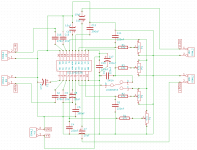
Your LM3886 is DC coupled on the output and AC coupled on the input (via C1)
Linear pots are often better matched between the two gangs than log types. Certainly in the cheaper varieties. Poor matching means the image can shift at low levels as the two channels track each other slightly differently.
You can "fiddle" a linear pot to a quasi log law which might be worth trying. Have a look at figure 8 here. You would have to scale the values to suit. And it's only the volume control that is normally a log law.
Potentiometers (Beginners' Guide to Pots)
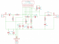
the AC coupling is OK.
He has C1 =1uF & R1 =22k RC=22ms
C2 =10uF R4=1k RC=10ms
You are using the amplifier as a filter. The very low RC of the NFB rolls off the bass signal far too early.
The amp should not be used as a filter.
Apply the filtering as passive at the input.
Change C2 >33uF and you might as well go the whole hog and fit either 150uF or 220uF with inverse parallel diodes (1n4002) across the cap pins.
You must fit CO1. This is the other input filter. I prefer it connected from R2 to Signal Ground. Not across the IN pins.
If you do take RF attenuation cap back to R2, then you need a low value resistor from -IN pin to the cap tapping point. use 100r or 220r.
- Status
- This old topic is closed. If you want to reopen this topic, contact a moderator using the "Report Post" button.
- Home
- Amplifiers
- Chip Amps
- LM1036 + LM3886, ON/OFF noise, DC offset and distortion