Question:
I built a basic "reference design" gainclone (one power supply, two channel sections) which worked well and sounds great connected to my econowaves. There's a "turn-on" thump, but I never thought much of it (I'd like to fix it, but it's low priority since I'm about to move and the workshop is being disassembled).
However, I have a more pressing concern. I hooked up my MP3 player and played a track; it worked fine until I shut down the amp first. My mp3 player now appears to be bricked. Is it possible there's enough spike feedback through the line in that it fried my player? If so, how would I diagnose and fix this?
It would be good to know the output impedance of your MP3 player, but failing that, we could assume 100 Ohms.
Connect 100 Ohms between the input of each gainclone channel and ground. Connect a digital scope, properly triggered, say at about 1/2 volt positive or negative. Then turn the gain clone on and off a bunch of times, try to capture the waveform across the 100 Ohm resistor. If you get much more than 1 Volt (either polarity), you probably have a problem.
Update My Dynaco

Something similar happened to me. Not with my gain clone though, no issues there.
Last thursday I was troubleshooting a pair of active speakers I made and I thought one of the amps might be the problem, so I wired it up like you're supposed to, turned it on, and poof my Macbook was dead.
I brought it in and they said they thought it was the logic board. $300 dollars to fix, and its 4 years old. So nearly $1500 later I'm replying from my new mac
I've never seen this unless the amp circuit has an issue. I blew my CD player's output after building an amp. I tie the ICs direct to the heat sink for the best thermal conduction, but of course, that puts the negative rail on the sink. During assembly, I somehow pinched the input wire against the heat sink and you can guess what happened!
Huh, it's a puzzler still. I hooked it up to an O-scope at work as djoffe suggested, but after attempting several power cycles, I never saw a peak-to-peak voltage difference of greater than 250 mV, and by far most of them were about 46 mV. Could my speakers have been at fault? I can't see how they'd feed back through everything, but I guess one never knows.
Curiouser and curiouser. I'm not dying to hook up my computer to this system yet, I can say that much. Visually all the appropriate groundy bits are tied to ground. Huh. Any other ideas?
Curiouser and curiouser. I'm not dying to hook up my computer to this system yet, I can say that much. Visually all the appropriate groundy bits are tied to ground. Huh. Any other ideas?
did you use a line out level or headphone jack out?
Might help to see the exact circuit around the input stage.
Suggestions to prevent this kind of problem would include adding a low value series input resistor (say 470ohm) and as suggested AC coupling.
If there is some bizzarre issue then a couple of inverse zeners and series diodes across the input to ground would kill any spikes and have no effect on the audio.
Headphone jack out. But I'm still mystified. Visually, input ground lines are connected to ground; I'll try to verify electrical connectivity tomorrow (I've had trouble recently with my ratchet crimpers crimping things all the way through the wires, but these appear pretty good). And I'd gotten tens of hours of use out of the amp itself; this definitely seemed connected to "shutdown thump" (which makes it even more puzzling that the O-scope didn't see anything significant).
Ye MP3 player seems pretty fried. Hooking it up to my computer's USB gives me the "USB device not recognized" error; no power that I've found is able to get any response from the thing. Luckily it's a pretty old Sansa e200, so not exactly a spendy device, but it was good for testing.
DigitalJunkie, I'm used to coupling caps being used to smooth power to chips; would have thought they'd interfere with signal if used on the audio input. I see in the audiosector.com instructions that he references protecting the AMP from DC offset, but I never considered protecting the input source.
I'm still weirded out by the lack of any significant voltage spike when connected to the O-scope. Should it make a difference whether speakers are connected? I left the amp at work, so I can check it out a bit more tomorrow...
Last edited:
Spikes can be hard to see as they are short duration. If they trigger the scope at the start of the sweep then you can easily miss them.
You could perhaps have two inputs to the GC. The direct and a "protected".
Ultimately you have to decide on whether there is a real design issue or fault here or whether it's a "characteristic" that needs to be "designed out" by AC coupling etc
If you posted the circuit it might help (to see the exact input stage) and there are basic tests that might reveal an issue.
Is there any DC difference between the 0Volts of the Amp and the 0Volts of the mp3 Player supply ?
I think the poster above is alluding to this also.
Zero volts is an arbitrary point.
For example, the zero volts of an MP3 player is still "its" zero volt point even if you were to connect the MP3 ground to an overhead power line. No current would flow and you could refer to this as "your zero volt reference" point.
A battery powered MP3 player ground will assume the potential of whatever it is connected to.
Its when you connect two points that you assume to be the same potential together and find they are not that you have problems.
If that makes sense
")
Spikes can be hard to see as they are short duration. If they trigger the scope at the start of the sweep then you can easily miss them.
I set the scope to trigger on a change with the trigger point in the middle of the screen, and I could generally see a TEEEENY change.
I hear you on zero reference points; on a completely different project, I was trying to supply a variable voltage from 0-20V (from a "reference ground" and "reference V+" to a third contact. Great, but it turned out that both the "0" and the "20V" were at about 90V and 110V with respect to case ground. Got some interesting zaps figuring that one out.
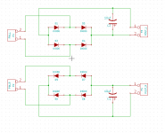
But not the case here. Here are the kicad schematics I made, using the reference design and the audiosector build instructions as guidelines; the audiosector build recommended changing the resistor I had as R5 (the 1K) on the input for a coupling capacitor if one was needed to protect the amp from a DC offset on input. And as mentioned, it worked and sounded great for hours and hours until this happened...
Attachments
Hmmm....
Hard to say for sure. A lot depends on what pin 7 (input) does as the rails rise at power on and collapse at power off. I'm thinking that if one rail collapsed first could there be a "parasitic" pathway through the chip allowing significant voltage to appear on pin 7.
In basic terms if say the supply is 30 volts (30-0-30) then a max of 30ma could be drawn from the 1K worst case and with a direct path to the full rail voltage. Could that zap a player...
Doesn't matter what all the theory and debating of this says... it's happened to you and the player is zapped. Was it the amp ? or just a natural failure of the player.
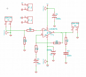
I can't see any problem AC coupling the input. Try a 4.7uf or 10 uf cap to the left of R4 and R5 junction. Also add another resistor to ground at the input side of the cap to ensure it never floats to a significant voltage if the input were unterminated.
Hard to say for sure. A lot depends on what pin 7 (input) does as the rails rise at power on and collapse at power off. I'm thinking that if one rail collapsed first could there be a "parasitic" pathway through the chip allowing significant voltage to appear on pin 7.
In basic terms if say the supply is 30 volts (30-0-30) then a max of 30ma could be drawn from the 1K worst case and with a direct path to the full rail voltage. Could that zap a player...
Doesn't matter what all the theory and debating of this says... it's happened to you and the player is zapped. Was it the amp ? or just a natural failure of the player.
I can't see any problem AC coupling the input. Try a 4.7uf or 10 uf cap to the left of R4 and R5 junction. Also add another resistor to ground at the input side of the cap to ensure it never floats to a significant voltage if the input were unterminated.
Bah, PCB mill is about to be torn down for a move, but I'll test it with a little hack and add a spot for one in the next revision (I'm trying to get this into a simple one-board kit form for some friends' kids, focus on simplicity rather than audiophile quality).
For my edification, when you say "to the left of R4 and R5 junction, also add another resistor to ground"--why not put it left of R5, between R5 and R4, with R4 taking the role of "another resistor to ground at the input side"?
Still learning (my background is mostly software and microcontrollers, so this signal processing business has me making a lot of silly mistakes).
I don't see how the input from your chipamps could fry anything through the 1k resistor. Even a 30v spike on the chip input could only produce 30ma through the resistor.
What would be able to do something would be a ground differential. That could happen if the mp3 players ground is different from the amplifier. Can you check for a voltage between your amps ground and the ground of your mp3s power supply?
What would be able to do something would be a ground differential. That could happen if the mp3 players ground is different from the amplifier. Can you check for a voltage between your amps ground and the ground of your mp3s power supply?
Like this. The resistor can be around 100K. It adds nothing noise wise because it is shunted by the source impedance as soon as anything is connected. The cap as mentioned can be around 4.7 to 10uf.
A practical point is that the polarity (and an electroylitic is fine... really) is best determined by measuring the DC voltage across it when no input is connected. Depending on the offsets of the IC the polarity could be either way so fit the caps accordingly. Same applies for your C1.
Also for minimum offset the value of R2 should normally equal R4+R5 so as to equalise the DC bias currents flowing from the two input pins.
A practical point is that the polarity (and an electroylitic is fine... really
) is best determined by measuring the DC voltage across it when no input is connected. Depending on the offsets of the IC the polarity could be either way so fit the caps accordingly. Same applies for your C1. Also for minimum offset the value of R2 should normally equal R4+R5 so as to equalise the DC bias currents flowing from the two input pins.
Attachments
- Status
- This old topic is closed. If you want to reopen this topic, contact a moderator using the "Report Post" button.
- Home
- Amplifiers
- Chip Amps
- My gainclone ate my mp3 player?