Well, MFD often does stand for MicroFareD on some schematics and parts lists, while mF is always millifared. Generally, hobbiest materials don't use millifared measures. However, textbooks do sometimes use millifared for formulas. You'll just have to look at the design and spot where the figures might be implausibly 1000 times off the mark.Thanks danielwritesbac, for clearing my confusion about micro farads and milli farads. The local electronic guys here are very lazy to perform conversions and differentiate between different units of measurements. They sometimes even, call microfarads as MFD in short.
Not practically. Remember your input signal is theoretically fixed at 20hz to 22khz, aka "The Audio Band" and now if you change a 40hz roll-off to a 5hz roll-off, you've dramatically Increased.Theoretically, you seems correct, and i want to agree with your answer, but two points are still disturbing me a very long last. Sorry! its a little bit off topic.
Gain bandwidth product is a constant value for every chipamp. So, if we increase the bandwidth, gain will decrease or if we decrease the bandwidth, gain will increase, and vice-versa. Now, by. . . increasing the value of the NFB Capacitor, didn't we increasing the Bandwidth (which in turn leads to decrease in gain)?
But notice that I had limited my answer earlier. Here's the other half: Compare a cap (to reach at least 5hz) with a short (dc couple). Which one has louder dynamics? There's always some catch-n-release going on when passing ac through a cap, so the quiet gets quieter and the loud gets louder. Yes, it is louder than the short. And yes, the dynamics are bigger with the cap.
This boost is pleasant when the cap is big enough. But if the cap is too small, a bit of compression can occur as the signal gets smashed and while a little bit makes warm bass, the usual problem is more vast and often arriving at a loud unpleasant boost of noise on ear sensitivity peak, such as with the Chipamp.com kit's far too small NFB cap and the resulting amplifier tirade that might be useful for a burglar alarm. The tone of too small cap problem is harmonic corruption that cannot be fixed by EQ. In this case, we need to repair the amp prior to considering buffer/preamp additions.
HA! Back on topic.
")
Now, for the sake of staying on topic, look at the chip-amp.com kit and assume that the power board is edge to edge with amp board (dual mono config) for zero length umbilical and big dampening so we don't have to buy any more caps And assume that I have swapped the 100u from the mute for the 47u NFB cap, again trying to fix the board without buying more caps. Now the NFB cap is 100u. Can you calculate the feedback-shunt resistor value from that aiming for a slightly warm bass tone? And now calculate the feedback resistor value for a gain of at least 30, without exceeding 110K (insufficient feedback current). There will be a slight compromise. Hint: E24 values are acceptable.
Successful calculation will relocate most of the screaming midrange distortion of the kit to several octaves lower, away from ear sensitivity peak and thus give a partially successful repair for the tiny price of two resistors.
P.S.
Remaining distortions of the kit include the too small amp board power caps (see NatSemi document An1192--470u minimum) and the board layout hindering stability (see 330p cap from in+ to in-, value from AudioSector LM4780 support, and Install location mentioned in Natsemi document LM3886.pdf as an "optional" yet vital part), and see Input Groundlift resistor which can be installed "standing up" in the CG port to elevate small signal up off the board, effectively retro-fitting the layout from bus to star ground. The output RC of the kit is wrong value because of efficient cap, so either change the output RC's cap to a lossy polyester dip cap intended by Natsemi -or- change the resistor to 5.6R.
P.P.S.
With most commercial gainclone kits, we end up either trying to swamp the board's midrange noises -or- throw the board away and run over to Decibel Dungeon for something level that also runs with cooler stability. Decibel Dungeon also illustrates the preamps and buffers.
Last edited:
Question:
Do you want the preamp to help a have-not source device play louder? Or do you want the buffer to help a have-not source device play with reduced current noise and thus a more level frequency response? Or do you want the buffer to help an inverting amplifier?
P.S. Example of a have-not source device--it may not have enough output and it does not have an output buffer. These are prone to current noise, lackluster bass and overall distortion if turned all the way up. A buffer or preamp turns the have-not source in to a have-plenty source. This is the main difference between a $13 economy Via Tremor sound card straight off the dac versus an M-Audio sound card with a few cents worth of op-amps added for onboard preamp. Of course, computer preamp projects are very popular.
Thanks! Mr.Daniel,
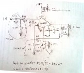
1.Feedback shunt resistor is 680R(chipamp lm3886-manual.pdf) with nfb cap as 47uf. NFB Resistor is 22K. This gives the gain of: 33.352941176470588235294117647059(V/V) ~ 30.462682750292653027043159545693 ~ 30.5db
With this combination, lower roll off is at: 4.9791711313234477533581521778098 ~ 5Hz
For the same roll off and 100u nfb capacitor,
F = 1/(6.284*R*(100*10^-6)), or,
R = 1/(6.284*F*(100*10^-6))
Since, F = 4.9791711313234477533581521778098.
R = 1/(6.284 * 4.9791711313234477533581521778098 * (100*10^-6)) = 319.60000000000000000000000000005
R = 319.6 ohms.
Now, keeping the gain same as before (30.5db), we can calculate the NFB resistor value as follows:
Gain = 1+Rf/R3 = R3+Rf\R3,
Gain*R3 = R3+Rf,
(Gain*R3) - R3 = Rf or,
Rf = (Gain*R3) - R3,
Rf = ((33.352941176470588235294117647059*R) - R), since, R3 = R(NFB shunt resistor),
Rf = ((33.352941176470588235294117647059 * 319.60000000000000000000000000005) - 319.60000000000000000000000000005),
Rf = (10659.599999999999999999999999999 - 319.60000000000000000000000000005),
Rf = 10339.999999999999999999999999997 ~ 10.34K.
So, the new values of the NFB shunt resistor is 319.6R and NFB resistor (Rf) is 10.34K(we can use nearby values or try different combinations) with new NFB capacitor being 100uf and the gain produced by the combination of new resistors is the same as earlier i.e 30.5db
2. Actually, my problem is not with a distorted mid sound. I have a boombox Model no. SANYO M6900. It consists of a chipamp designed around TA7769P(datasheet not available in english) which is PIN compatible with KIA6269P(datasheet available in english)
Sorry! its totally off the topic.
please, check out:
KIA6269P Datasheet pdf - 1.2W Dual Power Amp. - Korea Electronics (KEC)
The actual circuit inside the boombox uses 47uf(c1,c2) as the NFB capacitors for stereo left and right channels, and 33R(Rf1,Rf2) is used in series with the internally fixed feedback shunt resistor of 30R(so, the total is 66R feedback shunt resistor). NFB resistor is internally fixed to 20K, inside the chip.
Now, when i changed this 47uf NFB capacitor to 100uf (not touching any other component). I feel the improved bass performance and more dynamics and wide soundstage and low distortion at low frequencies. This was really a pleasant surprise for me BUT this comes with a side effect. I feel the suppresion of the sound at higher frequecy level. Higher tones were reduced in level and i felt as if the overall gain has been reduced, somewhat.Higher audio pitches were almost lost and the bass seems the dominant, only. It seemed, that somebody has choked the neck of an amplifier to not to produce the higher frequencies clear and normally loud enough to be heard. Overall balance of higher and lower frequencies was almost disturbed in the output. Yet, no distortion and the sound was more lively and more clear.This really disapointed me.
Unfortunately, the disapointment was more than the pleasant surprise.
So, i changed the value back to 47u, with simple sound and no base and no dynamics and no richness in sound.
Can you please, make me understand this, and tell me the way to keep the 100uf in place of 47uf with no side effects or other bad disruptions to sound?
This phenomena has the same side effect in almost all of the boomboxes, whenever, i change or increse the NFB capacitor, without changing any other component.
3.I want the buffer to help a have-enough source device play with far more reduced current noise as well as helping the main amp(as preamp) in sharing some gain load(redistribute gain) around 10db maximum for even far low noise, far low distortion and higher S/N ratiffcourse, also as an inverting opamp helper(buffer+preamp) sometimes, when i want to use the baxandall.
Thanks!
Now the NFB cap is 100u. Can you calculate the feedback-shunt resistor value from that aiming for a slightly warm bass tone? And now calculate the feedback resistor value for a gain of at least 30, without exceeding 110K (insufficient feedback current). There will be a slight compromise. Hint: E24 values are acceptable.
1.Feedback shunt resistor is 680R(chipamp lm3886-manual.pdf) with nfb cap as 47uf. NFB Resistor is 22K. This gives the gain of: 33.352941176470588235294117647059(V/V) ~ 30.462682750292653027043159545693 ~ 30.5db
With this combination, lower roll off is at: 4.9791711313234477533581521778098 ~ 5Hz
For the same roll off and 100u nfb capacitor,
F = 1/(6.284*R*(100*10^-6)), or,
R = 1/(6.284*F*(100*10^-6))
Since, F = 4.9791711313234477533581521778098.
R = 1/(6.284 * 4.9791711313234477533581521778098 * (100*10^-6)) = 319.60000000000000000000000000005
R = 319.6 ohms.
Now, keeping the gain same as before (30.5db), we can calculate the NFB resistor value as follows:
Gain = 1+Rf/R3 = R3+Rf\R3,
Gain*R3 = R3+Rf,
(Gain*R3) - R3 = Rf or,
Rf = (Gain*R3) - R3,
Rf = ((33.352941176470588235294117647059*R) - R), since, R3 = R(NFB shunt resistor),
Rf = ((33.352941176470588235294117647059 * 319.60000000000000000000000000005) - 319.60000000000000000000000000005),
Rf = (10659.599999999999999999999999999 - 319.60000000000000000000000000005),
Rf = 10339.999999999999999999999999997 ~ 10.34K.
So, the new values of the NFB shunt resistor is 319.6R and NFB resistor (Rf) is 10.34K(we can use nearby values or try different combinations) with new NFB capacitor being 100uf and the gain produced by the combination of new resistors is the same as earlier i.e 30.5db
Successful calculation will relocate most of the screaming midrange distortion of the kit to several octaves lower, away from ear sensitivity peak and thus give a partially successful repair for the tiny price of two resistors.
2. Actually, my problem is not with a distorted mid sound. I have a boombox Model no. SANYO M6900. It consists of a chipamp designed around TA7769P(datasheet not available in english) which is PIN compatible with KIA6269P(datasheet available in english)
Sorry! its totally off the topic.
please, check out:
KIA6269P Datasheet pdf - 1.2W Dual Power Amp. - Korea Electronics (KEC)
The actual circuit inside the boombox uses 47uf(c1,c2) as the NFB capacitors for stereo left and right channels, and 33R(Rf1,Rf2) is used in series with the internally fixed feedback shunt resistor of 30R(so, the total is 66R feedback shunt resistor). NFB resistor is internally fixed to 20K, inside the chip.
Now, when i changed this 47uf NFB capacitor to 100uf (not touching any other component). I feel the improved bass performance and more dynamics and wide soundstage and low distortion at low frequencies. This was really a pleasant surprise for me BUT this comes with a side effect. I feel the suppresion of the sound at higher frequecy level. Higher tones were reduced in level and i felt as if the overall gain has been reduced, somewhat.Higher audio pitches were almost lost and the bass seems the dominant, only. It seemed, that somebody has choked the neck of an amplifier to not to produce the higher frequencies clear and normally loud enough to be heard. Overall balance of higher and lower frequencies was almost disturbed in the output. Yet, no distortion and the sound was more lively and more clear.This really disapointed me.
Unfortunately, the disapointment was more than the pleasant surprise.
So, i changed the value back to 47u, with simple sound and no base and no dynamics and no richness in sound.
Can you please, make me understand this, and tell me the way to keep the 100uf in place of 47uf with no side effects or other bad disruptions to sound?
This phenomena has the same side effect in almost all of the boomboxes, whenever, i change or increse the NFB capacitor, without changing any other component.
Do you want the preamp to help a have-not source device play louder? Or do you want the buffer to help a have-not source device play with reduced current noise and thus a more level frequency response? Or do you want the buffer to help an inverting amplifier?
3.I want the buffer to help a have-enough source device play with far more reduced current noise as well as helping the main amp(as preamp) in sharing some gain load(redistribute gain) around 10db maximum for even far low noise, far low distortion and higher S/N rati
ffcourse, also as an inverting opamp helper(buffer+preamp) sometimes, when i want to use the baxandall.Thanks!
Last edited:
Select an available capacitor value for the NFB. Find the correct resistor value that gives the RC you want. Adjust the resistor to the nearest available value.
Use your required gain to arrive at the other NFB resistor, adjust to nearest available.
Now find the PSU and Input filters that match that set of NFB values actually used.
I suspect the dominating, overly strong, bass is due to poor speakers that are exaggerating the upper bass content to simulate deep bass.
That high Q bass could be a high value resistor in series with the bass driver. Long skinny cables, or thin wire in an air cored inductor.
Or, simply selecting a box that is too small.
Last edited:
The sport of tweaking the NFB cap. . .
Plan A, Simple Bypass (treble bypass):
Collect 5 different models of 100u (or larger) cap, try them and retain the best in-circuit. Collect 5 different values of dip cap (inexpensive polyester cap) and try them as bypass for your 100u cap to improve treble quality. Ceramic of smaller sizes can also work, but maybe not as rich (if too big). However, 0.47u or 0.22u Electrolytic bypass caps may be the easiest answer when you need larger size bypass caps.
Sizing by type:
Tiny value, 5n or less: Ceramic
Small value, 5n to 150n: Polyester
Larger values, 220n and up: Electrolytic
Plan B, Override Bypass (composite nfb cap):
Put the 47u back in circuit.
Solder one pin of the 100u to the chip-side pin of the 47u
Solder one pin of a 3.3 ohm resistor to the groundside pin of the 47u
Connect the free pins of the 100u and 3.3R (forming an RC bypass).
The 100u has now been "disadvantaged" by 3.3R higher ESR.
The 47u is now able to "override bypass" the 100u, except for lower pitches.
Looks like:
High ESR 100u bypassed with Low ESR 47u.
(inefficient 100u bypassed by efficient 47u)
P.S.
See that Plan A has the treble bypass least efficient and engaged when needed. However. . .
See that Plan B has the treble bypass most efficient and always on, with bass engaged as needed.
If one way doesn't work, try the other.
The actual circuit inside the boombox uses 47uf(c1,c2) as the NFB capacitors for stereo left and right channels, and 33R(Rf1,Rf2) is used in series with the internally fixed feedback shunt resistor of 30R(so, the total is 66R feedback shunt resistor). NFB resistor is internally fixed to 20K, inside the chip.
Now, when i changed this 47uf NFB capacitor to 100uf (not touching any other component). I feel the improved bass performance and more dynamics and wide soundstage and low distortion at low frequencies. This was really a pleasant surprise for me BUT this comes with a side effect. I feel the suppresion of the sound at higher frequecy level. Higher tones were reduced in level and i felt as if the overall gain has been reduced, somewhat.Higher audio pitches were almost lost and the bass seems the dominant, only.
Plan A, Simple Bypass (treble bypass):
Collect 5 different models of 100u (or larger) cap, try them and retain the best in-circuit. Collect 5 different values of dip cap (inexpensive polyester cap) and try them as bypass for your 100u cap to improve treble quality. Ceramic of smaller sizes can also work, but maybe not as rich (if too big). However, 0.47u or 0.22u Electrolytic bypass caps may be the easiest answer when you need larger size bypass caps.
Sizing by type:
Tiny value, 5n or less: Ceramic
Small value, 5n to 150n: Polyester
Larger values, 220n and up: Electrolytic
Plan B, Override Bypass (composite nfb cap):
Put the 47u back in circuit.
Solder one pin of the 100u to the chip-side pin of the 47u
Solder one pin of a 3.3 ohm resistor to the groundside pin of the 47u
Connect the free pins of the 100u and 3.3R (forming an RC bypass).
The 100u has now been "disadvantaged" by 3.3R higher ESR.
The 47u is now able to "override bypass" the 100u, except for lower pitches.
Looks like:
High ESR 100u bypassed with Low ESR 47u.
(inefficient 100u bypassed by efficient 47u)
P.S.
See that Plan A has the treble bypass least efficient and engaged when needed. However. . .
See that Plan B has the treble bypass most efficient and always on, with bass engaged as needed.
If one way doesn't work, try the other.
Last edited:
Thanks for reply,
NFB Feedback resistor is fixed inside the chip. How can i change it? Please, see the datasheet diagram:
http://www.datasheetcatalog.org/datasheet/kec/kia6269P.pdf
I need to change this resistor to 9.5K, instead of 20K.
Thanks.
Use your required gain to arrive at the other NFB resistor, adjust to nearest available.
NFB Feedback resistor is fixed inside the chip. How can i change it? Please, see the datasheet diagram:
http://www.datasheetcatalog.org/datasheet/kec/kia6269P.pdf
I need to change this resistor to 9.5K, instead of 20K.
Thanks.
Thanks!
FIRST OF ALL I WOULD LIKE TO KNOW, WHAT REALLY INSIDE THE CIRCUIT CAUSED THIS PROBLEM?
Plan A seems to be very sensitive. My ears are not so perfect and sensitive that they can differentiate between the different capacitor effects and choose the perfect one.Testing and measuring instruments are better adapted to this.
Plan B has already stated drawback of least efficiency.I don't want to create unwanted anamolies inside the circuit.
Please, look at the problem from the perspective of assembly production line where, thousands of machines are required to be created with perfection and long term reliability.Could Plan A and Plan B modifications, meet this quality assurance?
If there is any genuine solution to this problem, i want to accept it.
I don't want to implement compromised modifications, which may later fail at any time, because i am thinking about this whole process and phenomena to achieve long term, perfect, genuine and reasonable solution with every machine that i encounter. It's not only the case of a single boombox.
If there is no solution for this problem, then i am ok with it. I will accept the truth.Peace of mind is also necessary along with any modifications performed.
However, i will definately see the difference between both of your plans, next time when i will open the boombox again, but sure i won't be able to keep them forever.
Mr. Andrews solution seems to be genuine but i suspect if it will really work or not? Did unmatched RC constants can cause so much disturbances in sound quality?
Thanks.
Last edited:
Yes! Right. Sorry! We are too much off the topic. I think i have gained a lot more suggestions, from this buffer gain stage suggestion thread. And, i can implement this experience gained to any chip, not only with LM3886.
By the way what happened to Mr.zakman35? Did he completed his project? I would like to see some great pics of his live working project. LM3886 has also to come my way, sooner or later, i am sure.
Thanks to all and specially to Mr.Andrew and Mr.Daniel.
By the way what happened to Mr.zakman35? Did he completed his project? I would like to see some great pics of his live working project. LM3886 has also to come my way, sooner or later, i am sure.
Thanks to all and specially to Mr.Andrew and Mr.Daniel.
Long term tests all successful. Yes, of course, quality assurance will succeed for manufacturers that understand capacitors.Please, look at the problem from the perspective of assembly production line where, thousands of machines are required to be created with perfection and long term reliability.Could Plan A and Plan B modifications, meet this quality assurance?
Plan A levels the treble harmonics and is popular because large electrolytic caps have treble roll off. Hard sound may result from oversize bypass cap, so choose the value smaller than that.
Plan B is specific to clarifying baritone harmonics so that you have clearer sounding midbass. Plan B, bari quality can be used in addition to Plan A, treble quality.
And, don't forget your amplifier board's power circuit, decoupling cap size versus filtering, and layout for midrange control.
By the way what happened to Mr.zakman35? Did he completed his project? I would like to see some great pics of his live working project. LM3886 has also to come my way, sooner or later, i am sure.
Hi noddy55, i am here doing my math as you did in order to calculate proper RC values according to Andrew's suggestions.
Anyway i start with a "simple" question about a buffer stage and i end up re-building my 8 channel amp from scratch
. But i guess this is what DIY is all about and i enjoy "almost" every moment of it.I decide to rebuild only 4 channels at the moment but i need to make some rearrangements inside the amps case in order to reduce cabling.
I decide to go for a point to point construction instead of pcb, but i still need to decide about filters - gain - input sensitivity, but mostly about the values - size of the caps.
Of course i will post my schematic for your comments before i build it.
RM may have insufficient current, suggest smaller value--see the kits for a possible reference point.
RI versus CI mismatch slightly because of assuming perfect cap, suggest bigger values for RI and RF--such as 2K2, 62k, which won't need a preamp.
22k input load may lack slightly, suggest 10k~12k input load to reduce dc pollution of the CI area.
There are performance aspects more important than having a non-inverting amplifier's feedback resistor same value as its input load.
Perhaps you need to test some options with one amp before soldering all four.
Aribitray bypass cap value applied to "1000u Panasonic" and instead suggest to Temporarily use a sample 1000u as either an NFB cap or an output cap while you select an attractive bypass cap for it--ideal bypass cap value is not always 100n. So, "eavesdrop" on that and find a good match but try to select the value within a plausible range. It doesn't have to be perfect--main point is to avoid causing peakish.
2.7R with 100n output RC infers that the 100n is a polyester dip cap with an ESR of approximately 4 ohms (the typical part selected for mass production amplifiers); however, if instead you use an efficient cap, then increase the resistor value to 5.6R in order to maintain approximately correct resistance value (2.7R is off the mark if efficient cap is with it).
Stability assistance part is missing--that is Part CC from the datasheet (range 220p to 330p). Any treble lack from installing that can be recovered by selecting attractive bypass caps ("Plan A" simple method) to add at CIN and also at CI, and since you want to do that anyway, suggest installing part CC prior to performing fine tuning. Do please consider the "Part CC" capacitor (lm3886 datasheet) to assure stability prior to doing any sort of fine tuning work.
Ideal topologies for LM3886 support include nesting, composite and current pump, like the MyRef-FE and those should be considered before investing a lot of time with LM3886.
If you're not using one of those designs, but you are doing a non-inverting LM3886, I suggest 2 more parts.
*From Allied Electronics, 1 of 250v 4.7uF Mallory SEK capacitor to use from V+ to V- at the chip, for cancelling audible harmonic noise. That's 1 of those caps per each chip. This filter can make your audio fine tuning easier and perhaps the amp may run a bit cooler.
*A buffer to help source devices input a more level frequency response--although a stiffer input load at the chip (my previous suggestion of 10k to 12k range) will help slightly, a buffer can help greatly, depending on the source used.
Last edited:
RF = 62K? I thought the maximum value for RF was close to 33K.RI versus CI mismatch slightly because of assuming perfect cap, suggest bigger values for RI and RF--such as 2K2, 62k, which won't need a preamp.
Yes, but this will decrease the input sensitivity to 1.4V, miniDSP outputs only 0.9 V.22k input load may lack slightly, suggest 10k~12k input load to reduce dc pollution of the CI area.
I have include CC 220pf, but instead of the usual position between +In and –In I have place it between +In and signal ground. This decision made after I read this thread.Stability assistance part is missing--that is Part CC from the datasheet (range 220p to 330p)
Are you suggesting to omit Cin & Ci?to add at CIN and also at CI, and since you want to do that anyway, suggest installing part CC prior to performing fine tuning
MyRef-FE, hmmmm, I have four chips left!!!Ideal topologies for LM3886 support include nesting, composite and current pump, like the MyRef-FE and those should be considered before investing a lot of time with LM3886.
I think i will not avoid the buffer after all.A buffer to help source devices input a more level frequency response--although a stiffer input load at the chip (my previous suggestion of 10k to 12k range) will help slightly, a buffer can help greatly, depending on the source used.
Divide the feedback resistor value and the feedback-shunt resistor value and then add 1, to check your gain settings. The feedback resistor versus the feedback-shunt resistor form a voltage divider, really just an ordinary volume control. If want lower resistor values then. . .RF = 62K? I thought the maximum value for RF was close to 33K.
For feedback of 33k the feedback shunt resistor is 1.2k (gain is 28.5x) and the NFB cap is in the range of 330u (warm) to 470u (neutral). Yes, you'll need a bigger cap. Those are more difficult to select for seemly results, but very much doable.
Both lower resistor values and higher resistor values represent trade-offs, but they're different.
Then decrease the 680R proportionately. For example, 10k with 330R at input. Loss or lack of a load in this area dramatically reduces the performance of the amplifier's LTP type input. That chip is not an integrated amp--it is a power amp. The actual sensitivity is the amplifier gain setting, and if that is looking too high (too much influence and noise) then consider a preamp. I would consider the MooseFet project.Yes, but this will decrease the input sensitivity to 1.4V, miniDSP outputs only 0.9 V.
The need of these options will be different per each different layout.I have include CC 220pf, but instead of the usual position between +In and –In I have place it between +In and signal ground. This decision made after I read this thread.
I wouldn't omit those caps. Even though there's a selection workout, there's grand performance benefits to be had, especially in dynamics. And, always zero offset is helpful for speaker safety.Are you suggesting to omit Cin & Ci?
Have fun!MyRef-FE, hmmmm, I have four chips left!!!
Depending on the source, the frequency response can be helped with a buffer. My computer is a good example of that. Even my 6n3p experiment (no match for a diamond buffer) still managed to improve the computer's output tremendously, and that was a surprise. How much? Well, throw the EQ away--that much.I think i will not avoid the buffer after all.
Yes, surprising indeed.
Last edited:
I would like to thank you all for helping me understand and build this amp.
I build 4 channels point to point construction.
The measure: DC offset 1,4 - 1,7 mV, Ac noise = 0.1mV.
Listening impressions: the amps are more detailed and noise free.
I can hardly listen to a tiny hiss with my ear stuck on the tweeter and preamp at full volume.
Here is the final schematic i use.
I build 4 channels point to point construction.
The measure: DC offset 1,4 - 1,7 mV, Ac noise = 0.1mV.
Listening impressions: the amps are more detailed and noise free.
I can hardly listen to a tiny hiss with my ear stuck on the tweeter and preamp at full volume.
Here is the final schematic i use.
Attachments
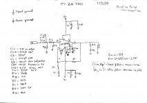
I wonder if you might like up to triple the values of both RI and RF. When done proportionately, it doesn't change the gain. But, it does change the feedback current and that will give you a different sound that you may (or may not) like better.
H1/H2 bass tone:
For one thing, adjusting RI up to the neighborhood of 2K~2.7K will match up with that 220uF at CI for neutral tone setting or 1k~1.5K with 220uF for warm bass setting.
Likewise adjusting RI up to approximately 1K~1.5K will match up with a CI value of 470uF for neutral tone setting or 680R with 470uF for warm bass setting.
However, the schematic's 680R with 220uF is "extra extra warm" bass setting that some people might think is either boomy or "old fashioned" sort of bass rendering, and yours won't be boomy thanks to Cin set at 1u.
2 ways to make CI "larger" (pass more/lower bass):
Larger values for CI (a bigger cap or a paralleled cap), or. . .
Larger values for RI (increase RF resistor by same proportion to keep gain)
H1/H2 balance is also reliant on Cin, input cap, size, and I believe that 0.68u to 3.3u values are valid choices--the schematic's 1u looks valid to me. At the input cap, smaller is cleaner; however, if Cin is made proportionately larger, likewise CI may also be made larger resulting in more low notes and with the same tone balance as before. But if Cin is made larger without making CI larger then the result is warmer/boomier bass. Conversely, if Cin is not changed but CI made larger, then the result is colder/deeper bass.
Currently, the schematic has CI set for warm warm and Cin set for clean. Given that LM3886's Spike system can cause "hot mids" sound, your setting for extra warm, yet clean, bass may be a practically perfect tonal balance compensation. Is that a "bari boost" setting? I do believe that your schematic shows a valid option for LM3886 and other overture chips. I've listed other bass options in case you want to try them.
Last edited:
Cin= 10uf,
Thanks for the us-full infos, i do have some modules left so maybe i will try a version with increased Ci and one increased RI and RF.
The bass settin and the effects of it varies according to the used speakers and the room of caurse, for example with my Audio Spectrum Athena speakers (8'' Seas woofer, 1'' seas tweeter, F3= 33Hz) with active cross and bi-amplification the bass is definitely on the warm side but very pleasant and not boomie.
Today i connect (with passive crossovers no bi-amplification) my Focal's (Electra 906 with 6.5'' midwoofer, 1'' tweeter, F3 = 50Hz) which i rarely use because their lack of lower bass and i notice a significant increase in the lower extension (5 - 10 Hz i guess) with very natural bass tones, no warmness here.
The Focal's now sound full bodied and very natural and they certainly don't lack bass any more.
So my question is, can the adjustment of Ci & Ri effect beside the bass tone & the bass extension as well?
- Status
- This old topic is closed. If you want to reopen this topic, contact a moderator using the "Report Post" button.
- Home
- Amplifiers
- Chip Amps
- Buffer/Gain stage suggestions for LM3886