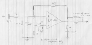
Hereby the schematic of the LM3886 without an electrolytric feedback capacitor. Such electrolytic capacitor may introduce distortion and therefor it is better to drop it.
But how to prevent a (multiplied) DC offset voltage at the output?
By inserting an extra resistor to the negative input, you can balance out the offset voltage. This extra resistor is short-circuited for AC signals by a capacitor, but this capacitor can be a MKT/MKP type of lets say 1 microF.
The value of the resistor is determined experimentely and I found 27 Kohm for one (see the schematic) and 18 Kohm for the other amplifier. The offset voltage is then only 0,9 milliVolt respectively 0,2 miliVolt !! This offsetvoltage doesn't run away through varied circumstances, like power, temperature etc.
I am very suprised that this method is not applied more often. Please give your comments.
Marc.
Attachments
Nice idea with some demerit. You simply made better symmetry of input bias currents paths. But the thermal drift of input voltage and current offsets will be still multiplied by 20. Electrolytic C makes this factor to be 1.
In your circuit I wouldn't put the shunt C at all.
In your circuit I wouldn't put the shunt C at all.
Thanks ddd,
I do agree that the thermal drift of input voltage and current offsets will be still multiplied by 20. But how much will that be in reality? All the components are closely to each other on one chip.
I made the chip clipping and oscillating with a high voltage and high frequency input signal, so it got warm. Directly after that I measured the output offset voltage. The difference was in the range of less than 1 milliVolt.
You need the input capacitor because of
- the chance that there is a DC voltage on the input signal;
- if the input has a low DC resistance, then the symmetry will be broken.
I recommend the capacitor parallel to the extra resistor to the negative input because it decreases the chance of high frequency oscillations. This is an experience I have with building more amplifiers in the past.
Marc.
ddd,
1. The C shunt (in my schematic the C parallel to the resistor of 27 K) doesn't cause oscillations: on the contrary!
Of course I measured without the C shunt and then you see some overshoot on the edges of blocksignals of 50 kHz and more. With the C shunt the blocksignals have smooth edges but it doesn't change the slew rate. I measured almost 15 V/microsec.
If you put a high signal (more than 3 V p-p) which a high frequency (more then 200 kHz) on the input (without an input filter), the amplifier will clip. If you make the input voltage higher and higher, you force the amplifier to oscillate. The C shunt makes that the amplifier will oscillate a little bit later.
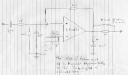
2. Indeed the data of the offsets are given in the datasheet within broad limits. In practice all examples of the LM3886 have different input offset voltages and currents. What you do is adjusting the value of the resistor (in my schematic the resistor with the value 27K) in such way untill the output offset voltage is 0,00 V. For one amplifier I found a value of 27 K and for the other a value of 18 K. The output offset voltage is then only 1 - 2 millivolt!! And this output offset voltage hardly drifts when the amplifier gets hot.
So with only this extra resistor and by - experimentely - adjusting its value, you can tune out the effects of the (differences in) input offset voltages and currents.
Marc.
1. The C shunt (in my schematic the C parallel to the resistor of 27 K) doesn't cause oscillations: on the contrary!
Of course I measured without the C shunt and then you see some overshoot on the edges of blocksignals of 50 kHz and more. With the C shunt the blocksignals have smooth edges but it doesn't change the slew rate. I measured almost 15 V/microsec.
If you put a high signal (more than 3 V p-p) which a high frequency (more then 200 kHz) on the input (without an input filter), the amplifier will clip. If you make the input voltage higher and higher, you force the amplifier to oscillate. The C shunt makes that the amplifier will oscillate a little bit later.
2. Indeed the data of the offsets are given in the datasheet within broad limits. In practice all examples of the LM3886 have different input offset voltages and currents. What you do is adjusting the value of the resistor (in my schematic the resistor with the value 27K) in such way untill the output offset voltage is 0,00 V. For one amplifier I found a value of 27 K and for the other a value of 18 K. The output offset voltage is then only 1 - 2 millivolt!! And this output offset voltage hardly drifts when the amplifier gets hot.
So with only this extra resistor and by - experimentely - adjusting its value, you can tune out the effects of the (differences in) input offset voltages and currents.
Marc.
ddd,
I appreciate that you will try it soon.
Indeed in the datasheet the input offset voltages and currents vary 10 times but that is between different examples. Within one example, the offset voltage and current will vary much less.
My experience is that the typical value applies to the most examples following the Gausse curve. See note 10 in the datasheet. The limit value is the guaranteed value for a single example. See note 11.
By adjusting the value of the resistor, you can cancel the difference between different examples.
I hope to hear your practical results.
Marc.
Agree. Furthermore even worst chips will get better symmetry.
The method could be applied in case with electrolytic C as well, improving further the offset.
The shunt C could be possibly by far less, taking account of its anti-oscillation role only.
PS. In case with electrolytic C the R(+in -> earth) will have intentionally a little bit higher value to provide adjusting headroom. Or your idea can be accomplished just changing this R without additional one.
Avoiding el. C is the basic value of your method anyway.
Last edited:
Thank you for your question. I do not understand why there is so little interest in a solution to avoid the electrolytic feedback capacitor and still have almost no DC offset voltage.
No, this extra resistor doesn't effect the gain of the amplifier for two reasons. The first one is that the input resistance of the amplifier is so high that the extra resistor is very very small compared to the input resistance. The second reason is that the extra resistor is short-circuited by the capacitor of 1 microF, although the main reason for this capacitor is that it prevents the amplifier motorboating and oscillating. But even without this capacitor my amplifier didn't oscillating or motorboating so the capacitor of 1 microFarad is pure precaution.
No, this extra resistor doesn't effect the gain of the amplifier for two reasons. The first one is that the input resistance of the amplifier is so high that the extra resistor is very very small compared to the input resistance. The second reason is that the extra resistor is short-circuited by the capacitor of 1 microF, although the main reason for this capacitor is that it prevents the amplifier motorboating and oscillating. But even without this capacitor my amplifier didn't oscillating or motorboating so the capacitor of 1 microFarad is pure precaution.
I happen to own the very nicely written book "Designing Audio Amplifiers" by Bob Cordell. Your suggested LM3886 circuit is exactly the same as Figure 8.3b on page 158. So, this is not something new.
The chapter in which the figure is located discusses DC offset, and various techniques (including the usual electrolytic cap in an RC filter to ground from the negative feedback path). His comments on this topology are:
Say, while we are on the subject (hope that this is not thread hikacking), why don't people use a capacitance multiplier in place of the electro? The cap has a grounded terminal, so I believe that type of circuit can be used...
For example, substitute the terminal marked +C in the left most circuit in the figure in place of the usual grounded electrolytic, use a 1uF film for C1 and then select the resistor ratio to give you 100uF or 1000uF or whatever you need.
Thoughts?
-Charlie
The chapter in which the figure is located discusses DC offset, and various techniques (including the usual electrolytic cap in an RC filter to ground from the negative feedback path). His comments on this topology are:
"This arrangement reduces some of the input offset concerns without resorting to an electrolytic capacitor. However, the DC gain of the amplifiers is now equal to the closed-loop gain, so a big part of the advantage of having an electrolytic in the conventional arrangement is lost (due to input voltage offset). This approach can be used in combination with a DC servo to reduce the amount of correction that must be supplied by the servo."
So, while it seems you have removed an electrolytic cap, which is probably a good thing, it does away with the function of that cap as well. What's the overall advantage??? Not sure.Say, while we are on the subject (hope that this is not thread hikacking), why don't people use a capacitance multiplier in place of the electro? The cap has a grounded terminal, so I believe that type of circuit can be used...
For example, substitute the terminal marked +C in the left most circuit in the figure in place of the usual grounded electrolytic, use a 1uF film for C1 and then select the resistor ratio to give you 100uF or 1000uF or whatever you need.
Thoughts?
-Charlie
Hello Charlie,
I didn't say that my method is new.
What is new in my approach is that I adjust the value of the resistor to the -input so that the output is almost exactly 0,000 V. For one LM3886 amplifier this results in a value of 27 kohm and for the other of 18 kohm. As I posed in a thread before, this value is not influencing the amplification. I then heated the amplifiers by full powering them. This results in a output offset voltage of only a few milliVolts, but when you put down the power, the output offset voltage is returning to its original point
So I dont agree with Bob Cordell. In my approach you can compensate the input offset current and voltage by adjusting just one resistor, so that the output offset voltage is nearly zero volt (In my case only 1 - 2 milliVolt). I found out in practice with the LM3886 amplifier that this output offset voltage doesn't run away (In my case max. 5 milliVolt). I was amazed by this result myself.
So, despite of the fact that de DC gain is equal to the closed loop gain, you not "reduces some of the input offset" but you can almost fully cancel it out by adjusting one resistor!! And it is not running away.
The overall advantage is a quite stable output offset voltage of (nearly) zero while not needing an electrolytic capacitor.
Marc.
...why don't people use a capacitance multiplier in place of the electro? The cap has a grounded terminal, so I believe that type of circuit can be used...
Thoughts?
-Charlie
Dear Charlie,
I think it's mistake to try this.
The point +C has the offset of the new OpAmp, which could be significant (with 1MOhm resistors). And you connect it to very sensitive point, multiplying its DCV by 20. Instead of benefit you'll get harm. Not mentioning several new elements in comparison with simple resistor.
These circuits are gyrators (Wiki).
I am gussing that zeroing out any DC offset is a simple thing to do in the circuit, and as long as the capacitance scaling resistor is small compared to 1M the input impedances will be relatively well balanced anyway.
-Charlie
Hello Charlie,
I didn't say that my method is new.
What is new in my approach is that I adjust the value of the resistor to the -input so that the output is almost exactly 0,000 V. For one LM3886 amplifier this results in a value of 27 kohm and for the other of 18 kohm. As I posed in a thread before, this value is not influencing the amplification. I then heated the amplifiers by full powering them. This results in a output offset voltage of only a few milliVolts, but when you put down the power, the output offset voltage is returning to its original point
So I dont agree with Bob Cordell. In my approach you can compensate the input offset current and voltage by adjusting just one resistor, so that the output offset voltage is nearly zero volt (In my case only 1 - 2 milliVolt). I found out in practice with the LM3886 amplifier that this output offset voltage doesn't run away (In my case max. 5 milliVolt). I was amazed by this result myself.
So, despite of the fact that de DC gain is equal to the closed loop gain, you not "reduces some of the input offset" but you can almost fully cancel it out by adjusting one resistor!! And it is not running away.
The overall advantage is a quite stable output offset voltage of (nearly) zero while not needing an electrolytic capacitor.
Marc.
Your scheme is essentially the same as Cordell's, except you are trimming one of the resistors that is trying to balance input impedances. I think that by "trimming" the resistor, you are trimming out the input offset.
Did you try this with the regular scheme using the SAME LM3886 IC? It would be a better test to do a comparison between the two circuits holding everything else constant. There is part-to-part variation and it could be that the particular LM3886 chip that you are using just happens not to drift with temperature in the first place. Once you make the correction at one temp, then it would be valid at other too. Not sure, just trying to think up alternate explanations...
-Charlie
Hallo Charlie,
My scheme is the same as Cordell's but the essential difference is that I trim the resistor to a zero output offset voltage.
I made two amplifiers with different LM3886's. In theory the value of the trimming resistor is 20 kohm but in practice I found that the optimal value is 18 kohm for one amplifier and 27 kohm for the other amplifier. The output offset voltage is then 1 - 2 milliVolt in both cases !! I also found that in both cases the output offset voltage is running away for max. 5 milliVolt when heating the LM3886 chips.
So I don't agree with Bob Cordell that "a big part of the advantage of having an electrolytic in the conventional arrangement is lost (due to input voltage offset). This approach can be used in combination with a DC servo to reduce the amount of correction that must be supplied by the servo."
Using this trimming resistor there is no need for a servo because the output offset voltage stays very small. The overall advantage is no electrolytic capacitor.
Even Bob Cordell is not always right. I repeat my question why this solution is not often used?
Marc.
Attachments
[/QUOTE]
I'm not sure why it would not be used more often, except that it requires trimming, the feedback electrolytic cap is just NOT that bad, and there are other ways to trim that are probably preferable and cheaper. That's just a guess on my part, however.
-Charlie
Yes, that's what I said above in my post.Hallo Charlie,
My scheme is the same as Cordell's but the essential difference is that I trim the resistor to a zero output offset voltage.
You already mentioned this. Is this so much different than other methods of trimming out offset voltage in terms of stability?I made two amplifiers with different LM3886's. In theory the value of the trimming resistor is 20 kohm but in practice I found that the optimal value is 18 kohm for one amplifier and 27 kohm for the other amplifier. The output offset voltage is then 1 - 2 milliVolt in both cases !! I also found that in both cases the output offset voltage is running away for max. 5 milliVolt when heating the LM3886 chips.
No servo needed = correct. The problem is now that the amplifier will have large DC gain (Same as AC gain, e.g. 25-30x). Even though you have a HP input filter, this is not a good idea, but this is just my opinion.So I don't agree with Bob Cordell that "a big part of the advantage of having an electrolytic in the conventional arrangement is lost (due to input voltage offset). This approach can be used in combination with a DC servo to reduce the amount of correction that must be supplied by the servo."
Using this trimming resistor there is no need for a servo because the output offset voltage stays very small. The overall advantage is no electrolytic capacitor.
Even Bob Cordell is not always right. I repeat my question why this solution is not often used?
Marc.
I'm not sure why it would not be used more often, except that it requires trimming, the feedback electrolytic cap is just NOT that bad, and there are other ways to trim that are probably preferable and cheaper. That's just a guess on my part, however.
-Charlie
if the two input transistors are exactly matched and the two input sources resistances are exactly matched then the feedback ensures that the output offset is always zero.
The problem is that it is impossible to get the two inputs transistors exactly matched. You are using trimming of the source resistances to add a correction for the unmatched transistors.
You will find that the output offset will drift slightly. This drift may be so small that a servo is never needed.
- Status
- This old topic is closed. If you want to reopen this topic, contact a moderator using the "Report Post" button.
- Home
- Amplifiers
- Chip Amps
- LM3886 without electrolytic feedback capacitor and (hardly) no DC offset voltage