Did you compared the two amplifiers, yours against the Penasa?
If you mean the My_Ref Rev C Vs my variation (which in fact is a modded My_Ref), obvioulsy yes.
I have found the Penasa amplifier very good sounding but the sound is a bit dry comparing to other solid states desings.
How the My_Ref sound is related also on parts used.
BTW, IMHO, the My_Ref Fremen Edition sound better and different from the My_Ref Rev C, more refined with wider and deeper soundstage and a much tighter, controlled, deep bass.
Grigore,
If you dig a bit, you will find that Bob (bcmbob) made the comparison to a MyRef C with LF01 somewhere back in the FE Beta thread. Many would consider that the ultimate MyRef version. He found the FE a significant improvement.
I can't comment on that from personal experience, but I would like to echo Dario's comments on components. You said that the Penasa amp was a bit dry sounding. Following input from others on the forum, I have found that you can make a significant change is this kind of character just by the choice of DC blocking cap, C13, at the signal input. I have tried polyprop caps with aluminum, copper, and tin which all have different mixes of warmth, detail, and bass. For example, at the moment, I am using a 1 uF Russian K75 (hybrid of paper and polymer dielectric) paralleled by a 1 nF Amtrans polyprop. That is nicely warm and full with pretty good detail due to the small parallel cap.
So if you have a MyRef and want to improve it, there are lots of ways to go. If you don't have one, but are thinking of building, then Dario's FE is an excellent choice. It is the Penasa design, just with an improved, shunt style voltage regulator, a ground plane board design, and a few other minor improvements. One big thing is that Dario has spent a huge number of hours learning which components sound the best in this design. Whether you build using the premium or budget BOM, you have the advantage of a lot of detail work going into the choices. You know what they say, every component counts.
Jac
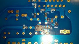
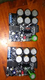
With some time off for the holidays I was finally able to get started on the FE boards! I spent a few hours yesterday soldering all of the SMD parts. Unfortunately I am pretty sure I have a solder bridge between two or more of the pins on one of the lm318. I have soldered a few SMDs before and I dont remember them giving me this much trouble.(though I did not have a quiet workspace where I could concentrate this time).
How resistant to heat are the lm318s? Can I rework them, or should I just order some replacements?
I am excited to finally be underway....and for the most part being done with the SMDs
Here is a pic....not really my best work but hopefully good enough for great sound!
How resistant to heat are the lm318s? Can I rework them, or should I just order some replacements?
I am excited to finally be underway....and for the most part being done with the SMDs
Here is a pic....not really my best work but hopefully good enough for great sound!
Attachments
Last edited:
With some time off for the holidays I was finally able to get started on the FE boards! I spent a few hours yesterday soldering all of the SMD parts.
Very good !
Unfortunately I am pretty sure I have a solder bridge between two or more of the pins on one of the lm318.
(...)
How resistant to heat are the lm318s? Can I rework them, or should I just order some replacements?
You can rework them, but you must be fast, use solderwick and flux to remove excess solder.
Do the same also for quite all resistors, way too much solder (you should never see a bubble).
BTW having at hands a spare LM318 can be useful if you later discover they were heated too much.
I see it now. Might take a few day's waiting, but Dario's favorite Chipquick process will handle it. I have had great results with the braid and regular liquid flux method also.
Using Chipquick.
Using Chipquick.
Bob, thanks for the video. that looks easy! I may try that or I may try the chipquik and solder wick. Not sure, but the bridge is hidden under the chip where I cant get to it without pulling off the whole ic. I am worried about all of the heat that has been applied, will be applied while removing the chip and will be needed to re-solder it. It might be best to order a few more from mouser and for now move on to some of the other areas of the board. hopefully I have not forgotten how to solder and the through hole components go right the first time
PS..I also killed a 10pf cap at C34 so I removed them both and replaced them with the alternate 27pf that I ordered with the BOM. I wish I had ordered extra 318s
PS..I also killed a 10pf cap at C34 so I removed them both and replaced them with the alternate 27pf that I ordered with the BOM. I wish I had ordered extra 318s
Spares are a good idea. However, if you use the end of the wick instead of the side, and trim the wick after about 1/4" has absorbed solder, you can draw a lot out with minimum heat. Two - four passes may be required. I heat the wick and then move the iron/wick combo into the solder on the board/chip. Liberal liquid flux on both the board and the wick.
Don't use a lot of downward pressure as the wick can be very abrasive.
Don't use a lot of downward pressure as the wick can be very abrasive.
CORRECTION!!
Here is a correction on my post #883.
"The LF03c is a dual DIP8 discrete opamp, so it won't electrically replace the LF01 .......... The LF03c is meant for DAC, CDP I/V, line stages, etc. which use dual opamps, and provides greater transparency than existing monolithics."
Sorry if I misled anyone. In any case, if it performs at a level matching the LFO1 it will be a valuable addition to the component/s in which it is installed.
progress
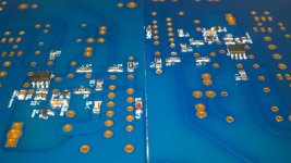
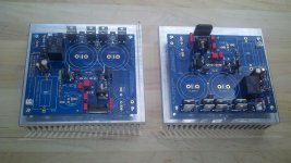
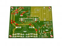
Well I finally have the majority of both of the boards populated with the exception of a few locations. I am expecting an order from mouser any day now with some replacement smd parts and the 220uf caps for c14 that I somehow omitted from my original order. Having said that I am going to replace most of the smd parts just to be on the safe side. It seems a few builders have had issues with that part of the process and now I feel like I have the hang of them I also have to decide what orientation I want to use for c9 and r10. Has there been a consensus reached on the ideal configuration?
I am also a little confused by the different values recommended for c10 22pf or 33pf. I did a quick search but I didn't find much info about this location and the values; any explanation would be great, I am sure I missed it along the way.
Ps. You can see in the photo that I absent mindedly installed a resister in one of the possible r10 locations
Well I finally have the majority of both of the boards populated with the exception of a few locations. I am expecting an order from mouser any day now with some replacement smd parts and the 220uf caps for c14 that I somehow omitted from my original order. Having said that I am going to replace most of the smd parts just to be on the safe side. It seems a few builders have had issues with that part of the process and now I feel like I have the hang of them
I also have to decide what orientation I want to use for c9 and r10. Has there been a consensus reached on the ideal configuration?I am also a little confused by the different values recommended for c10 22pf or 33pf. I did a quick search but I didn't find much info about this location and the values; any explanation would be great, I am sure I missed it along the way.
Ps. You can see in the photo that I absent mindedly installed a resister in one of the possible r10 locations
Attachments
I also have to decide what orientation I want to use for c9 and r10. Has there been a consensus reached on the ideal configuration?
From what I can remember everyone liked best the alternate config:
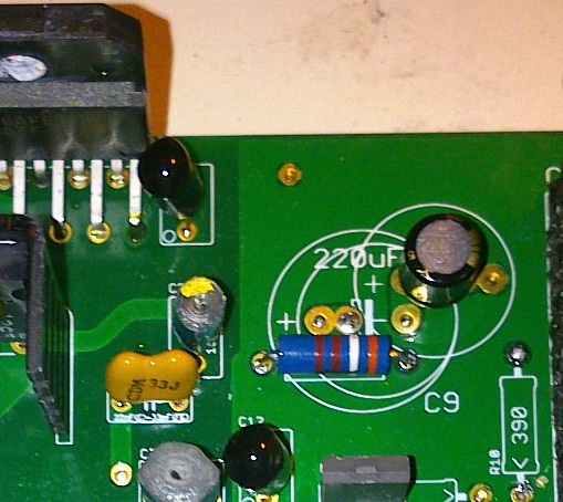
I am also a little confused by the different values recommended for c10 22pf or 33pf. I did a quick search but I didn't find much info about this location and the values; any explanation would be great, I am sure I missed it along the way.
Pay attention, C10 and C34 are linked and both have alternate values.
C10 and C34 are compensation caps.
The first one (C) is the MyRef Rev C original compensation by Mauro Penasa (the My_Ref designer), well tested and absolutely safe.
The second one (FE) is an alternate compensation, the official (but somewhat experimental) one for the Fremen Edition, and was determined by a trial and listen method by me with Siva's help (simulation and listening).
The (FE) compensation has proved to be stable and safe so far and sounds (much) better according my (and Bob's and others) ears.
Just for clarity:
Rev C compensation
C10 22pF
C34 10pF
Fremen Edition compensation
C10 33pF
C34 27pF
Ps. You can see in the photo that I absent mindedly installed a resister in one of the possible r10 locations
You'll probably desolder it...
Last edited:
Hi John,
yes, it sound better
Sadly no, maybe you could ask if one of the Release Candidate partecipants that buyed spare boards wants to sell them.
In the next months, though, there will probably be a group buy.
Hi This is last information I could find on the group buy . Dou you have any more plans for a group buy in the near future? I would like to buy the pcb's. Please keep us who are eagerly awaiting a chance to build your amplifier posted of any progress. Thanks for all the hard work you have done. I bet it sounds great!
Last edited:
Dou you have any more plans for a group buy in the near future? I would like to buy the pcb's. Please keep us who are eagerly awaiting a chance to build your amplifier posted of any progress.
The Group Buy for the final version will probably start this February.
The final PCBs are quite identical to RC ones with the following differences:
- some holes are larger
- no more alternatives for C9/R10 arrangement
- some DMM readings are indicated on PCB
Thanks for all the hard work you have done. I bet it sounds great!
You're welcome.
Sure it sounds great!
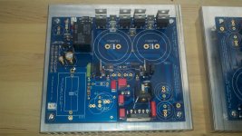
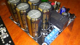
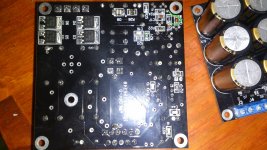
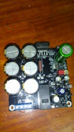
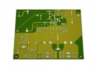
This is my design of this amplifier
Hi Svon,
interesting work but it seems a standard My_Ref, isn't it?
hopefully I ll become happy owner of this beauty
Are you referrring to the Fremen Edition or Svon's work?
Attachments
- Status
- This old topic is closed. If you want to reopen this topic, contact a moderator using the "Report Post" button.
- Home
- Amplifiers
- Chip Amps
- My_Ref Fremen Edition RC - Build thread