some pics below:
It look so terrific! I envy your building skills.

Off Topic
Bob,
Underground? In a way. Subwoofers are down at the bottom, grounded, if not underground.
I've been busy designing an upgraded signal board for my feedback subwoofer. I took suggestions from on components from Dario, gleaned pearls of wisdom from Dario, Andrew, and Tom, and studied the FE RC and other designs to come up with a board design. It just arrived as if a Christmas present.
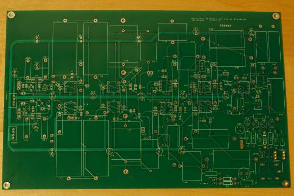
This is a bit larger than the FE boards. It as about 240 x 170 mm (9.5 x 6.5" for those of us stuck in the Victorian world). This is mostly a component and layout upgrade of my existing circuit. Among other goals, I wanted to keep most of my resistor values in the 1k to 10k range. That meant bigger capacitors (note the big rectangles on the board) and I chose to use high quality axial caps throughout. I used Susumu SMD resistors in the signal path and carbon film caps on traces to ground (thanks Dario). Following the lead of the FE, the design uses a ground plane. Most of the small components will be mounted on the side shown in the picture and that will be the bottom once installed. The big caps will be mounted on the top, ground plane side so that they are supported by gravity.
The most important part of the board for sound quality is the high pass crossover which feeds the FEs and the satellites. Since there are now 4 caps, including C13 on the FE, in series with the signal, I will play with different caps to get the right mix of sound. My first attempt will be an Audyn True Copper or a Jupiter HT paralleled by an FT-1 or small K71 in the first signal path position. That will be followed by K71s and K75 with a small parallel cap. I really like the K75 with an Amtrans in parallel as my current C13.
The low pass and feedback side are expected to be less critical for caps since they only pass 20 to 100 Hz. I am planning Mundorf Evo's and K40s as nice sounding, low cost caps with good bass.
Now I have to build and test it. Here is hoping everything works.
Jac
PS There is a bigger image of the board in my gallery. I can't seem to figure out how to get the thumbnails to copy over and expand when clicked. Sorry.
Glad to hear from you Jac - thought you had gone underground (like building a tube amp)
Bob,
Underground? In a way. Subwoofers are down at the bottom, grounded, if not underground.
I've been busy designing an upgraded signal board for my feedback subwoofer. I took suggestions from on components from Dario, gleaned pearls of wisdom from Dario, Andrew, and Tom, and studied the FE RC and other designs to come up with a board design. It just arrived as if a Christmas present.
This is a bit larger than the FE boards. It as about 240 x 170 mm (9.5 x 6.5" for those of us stuck in the Victorian world). This is mostly a component and layout upgrade of my existing circuit. Among other goals, I wanted to keep most of my resistor values in the 1k to 10k range. That meant bigger capacitors (note the big rectangles on the board) and I chose to use high quality axial caps throughout. I used Susumu SMD resistors in the signal path and carbon film caps on traces to ground (thanks Dario). Following the lead of the FE, the design uses a ground plane. Most of the small components will be mounted on the side shown in the picture and that will be the bottom once installed. The big caps will be mounted on the top, ground plane side so that they are supported by gravity.
The most important part of the board for sound quality is the high pass crossover which feeds the FEs and the satellites. Since there are now 4 caps, including C13 on the FE, in series with the signal, I will play with different caps to get the right mix of sound. My first attempt will be an Audyn True Copper or a Jupiter HT paralleled by an FT-1 or small K71 in the first signal path position. That will be followed by K71s and K75 with a small parallel cap. I really like the K75 with an Amtrans in parallel as my current C13.
The low pass and feedback side are expected to be less critical for caps since they only pass 20 to 100 Hz. I am planning Mundorf Evo's and K40s as nice sounding, low cost caps with good bass.
Now I have to build and test it. Here is hoping everything works.
Jac
PS There is a bigger image of the board in my gallery. I can't seem to figure out how to get the thumbnails to copy over and expand when clicked. Sorry.
Last edited:
Hey Jac, I really didn't understand what you were doing so I asked Mr. Google. Got this article. Is that the concept you are working with?
I gave up on the thumbnail thing. I use Xnview (Fantastic free program) to touch up and size the picture then save it to the desktop or some folder I'm using.
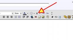
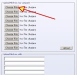
Then I select the "Attachment" icon in the menu bar. That opens a window with open slots for item selection. Navigate to the picture you want uploaded and repeat as needed. After those selections are complete, click on the "Upload" button. Wait for that to complete and close the window. Select "Preview" to confirm you have what you want and how it will look on the thread. If it is not what you want select the attachment icon again and kook for "Manage Attachments" where you can delete an item and replace it using the same process. When you are happy, do the actual post. The thirty minute edit time window is active, and you can edit text and/or go all the way back to advanced mode if that's what you need. Of course you have to be in advanced mode and not "Quick Reply" for this to work.
I gave up on the thumbnail thing. I use Xnview (Fantastic free program) to touch up and size the picture then save it to the desktop or some folder I'm using.
Then I select the "Attachment" icon in the menu bar. That opens a window with open slots for item selection. Navigate to the picture you want uploaded and repeat as needed. After those selections are complete, click on the "Upload" button. Wait for that to complete and close the window. Select "Preview" to confirm you have what you want and how it will look on the thread. If it is not what you want select the attachment icon again and kook for "Manage Attachments" where you can delete an item and replace it using the same process. When you are happy, do the actual post. The thirty minute edit time window is active, and you can edit text and/or go all the way back to advanced mode if that's what you need. Of course you have to be in advanced mode and not "Quick Reply" for this to work.
Attachments
Last edited:
Still off topic
Thanks Bob,
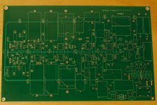
I didn't see the first screen you mentioned, but this is an attempt to attach something. I think it worked. Thanks.
As for your article, yes, it is essentially the idea. I'm using an accelerometer instead of dual voice coils. The advantage is that a bass speaker has a lot of distortion due to mass and suspension effects. A feedback subwoofer reduces the distortion significantly, sometimes by as much as 10 or 15 dB. Essentially, the feedback system measures the difference between the input signal and where the speaker coil moved. The power amp forces the speaker to move where it is supposed to be. The result is cleaner bass.
My father built one in the mid-80's and published an article in Speaker Builder, although companies like Velodyne sold very similar subwoofers before that. If my current project works, I'll have to do a forum project on the subject.
Thanks Bob,
I didn't see the first screen you mentioned, but this is an attempt to attach something. I think it worked. Thanks.
As for your article, yes, it is essentially the idea. I'm using an accelerometer instead of dual voice coils. The advantage is that a bass speaker has a lot of distortion due to mass and suspension effects. A feedback subwoofer reduces the distortion significantly, sometimes by as much as 10 or 15 dB. Essentially, the feedback system measures the difference between the input signal and where the speaker coil moved. The power amp forces the speaker to move where it is supposed to be. The result is cleaner bass.
My father built one in the mid-80's and published an article in Speaker Builder, although companies like Velodyne sold very similar subwoofers before that. If my current project works, I'll have to do a forum project on the subject.
Attachments
I've been busy designing an upgraded signal board for my feedback subwoofer. I took suggestions from on components from Dario, gleaned pearls of wisdom from Dario, Andrew, and Tom, and studied the FE RC and other designs to come up with a board design. It just arrived as if a Christmas present.
Wow Jac!
Really nice!
Thanks and thanks for your suggestions. I really did learn a lot from the FE and put those ideas into this board.
You're welcome
A little off topic
Has anyone ever tried to solder a component lead that doesn't want to wet with solder? If so, what can you do to correct this? I am updating some small capacitors in my subwoofer amplifier with some styrene capacitors and the solder won't stick to the leads. The parts come from Parts Connexion, so they should be reputable parts.
Jac

- Status
- This old topic is closed. If you want to reopen this topic, contact a moderator using the "Report Post" button.
- Home
- Amplifiers
- Chip Amps
- My_Ref Fremen Edition RC - Build thread