Capacitor Auditions, Redux
After having to take a few days out for normal life, I'm back to listening to capacitors in C13. I really enjoyed Tom and Andrew's discussion about brightness and clarity. In there own ways, both match the way I've been thinking about it, but with a way better explanation than I could have come up with.
Dario reminded me that I needed to check orientation. To be honest, I hadn't thought to do that, although I should have. As always happens, I managed to pick the wrong orientation for both the ZN and the True Copper. Of course, I had the right orientation for the K71, so I am batting 1000.
With the orientation of the True Copper switched, I understand what Tom and everyone have been talking about. The front to rear soundstage has improved and the clarity (as defined earlier by Tom and Andrew) improved. I could hear higher harmonics of strings and the size of the recording room more clearly without becoming hissy or harsh. I have the impression that the mid range is more forward and the overall sound is warmer. The bass is still amplified in my system, but this is more comfortable when there is not so much contrast to the mid range.
Listening again to the K71, they are still a touch cool in my system and the TC are now warmer. The K71 also have a lot of clarity and they have an equal or slightly better soundstage depth than the TC in the switched orientation. Overall, the K71 still sound very natural in my system, if a bit cool.
The switched orientation ZN are still forward in the mid range, but they have improved clarity and image. They feel more balanced than before and still very smooth and liquid. Wow, the choices just get tougher.
In the end, both the TC and K71 beat the ZN for clarity and image in my system. I think that, like Tom, the TC bass issue may disappear when I crossover the satellites as I believe the bass amplification is mainly below 100 Hz. That leaves me with a choice between cool and warm. I'll do some extended listening to the TCs before sending them back to Bob and decide what to order.
Jac
add in the snap action capacitor.
It builds up a higher voltage before the driver transistor conducts. Then when the transistor does conduct the relay coil sees the higher capacitor voltage for a few tens of milliseconds and that "snap action" occurs. After that short period of enhanced current availability, the cap has discharged down to the standing voltage available long term from the PSU and the relay holds in without consuming extra current/power.
This was all described in the earlier Threads and in a few other non related Threads. All it costs is a 22uF to 47uF 35V capacitor. It ensures correct triggering of the relay.
add in the snap action capacitor.
It builds up a higher voltage before the driver transistor conducts. Then when the transistor does conduct the relay coil sees the higher capacitor voltage for a few tens of milliseconds and that "snap action" occurs. After that short period of enhanced current availability, the cap has discharged down to the standing voltage available long term from the PSU and the relay holds in without consuming extra current/power.
This was all described in the earlier Threads and in a few other non related Threads. All it costs is a 22uF to 47uF 35V capacitor. It ensures correct triggering of the relay.
Andrew,
Very interesting. I search for "snap action capacitor" without results. Where are the putting the capacitor? Can you explain a bit more?
Thanks
Jac
Wow, the choices just get tougher.
I'll do some extended listening to the TCs before sending them back to Bob and decide what to order.
Jac
AMEN !!
Take all the time you need, cause if you have the caps I get a few weeks of relative sanity.

If you have it, run the Isotek process multiple times. I often start it in repeat mode and leave the house to do errands. For me, after about 4 half hour sessions there isn't much obvious change - - though I believe the system will continue to sweeten over additional weeks and months.
find the transistor and relay coil traces.
You need the cap to span across both the coil AND the transistor.
While the transistor CE is open circuit the cap charges at the RC rate set by the cap value and the preceding resistor/s. When the transistor CE becomes closed (high Ib makes the CE appear as a short circuit) the cap discharges through the coil.
I did not call it a snap action previously. Just a term that came into my head this time around.
I told Salas about the bad design of the relay driver. He would not take any action to correct the reliability of triggering fault.
I told Freman he had adopted a bad design even though I had previously posted a few times why it was a bad design. He too did not take action.
I repeatedly see problems reported on reliability of triggering.
It could have all been avoided if the original circuit had been thought about.
It would be interesting to determine if those builders with this problem ordered the BOM verbatim from Mouser or another supplier. I have always thought it is well worth the cost of a few extra dollars to start with an "as published" BOM. That approach has given a 4 for 4 successful initial power-up in my builds.
I'm still curious about what swapping the two relays would produce.
I'm still curious about what swapping the two relays would produce.
Last edited:
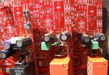
finally got Irfanview downloaded to my new PC.
Sorry about the dust, just picked them up off the shelf.
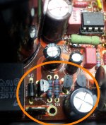
Note the two Zeners for R19 on the left.
All the drivers have a Zener in the circuit to increase the triggering voltage.
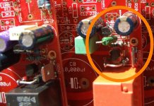
The right shows a link below and slightly to the right of C16. This is an extra resistor that comes under the PCB from R23
Note the series Zener and diode across the relay coil for faster release.
How I wish when editing that the Forum software did not lose attachments. I have had to attach again during each edit.
Sorry about the dust, just picked them up off the shelf.
Note the two Zeners for R19 on the left.
All the drivers have a Zener in the circuit to increase the triggering voltage.
The right shows a link below and slightly to the right of C16. This is an extra resistor that comes under the PCB from R23
Note the series Zener and diode across the relay coil for faster release.
How I wish when editing that the Forum software did not lose attachments. I have had to attach again during each edit.
Attachments
Last edited:
Marra,
I like Andrew's idea,it is a good approach for more reliable triggering. But if you are looking for a quick diagnostic check and your relay appears to trigger, then drop out again, this might be a quick check.
R14 is 470 ohm in the BOM. Using the 470, the simulation suggests that the relay should trigger at about 1 second, then drop to 14 to 15 V once engaged (assuming 22V transformer in my simulation). If the problem is that your relay doesn't stay engaged at 14 to 15 V, then you can try reducing the value of R14. Try 220 or 330 ohms and that will increase the engaged voltage by a few volts without risking the DC protection. Actually, your DC protection may take a little longer to actuate, but it should still work.
Jac
Yes, the smaller 220/330 ohm resistor works reliably with smaller transformers. I used one of those values (can't remember which) in my builds and I have NEVER had a relay fail to close or open at the appropriate time. My amps have been turned on and off every day for a more than a year.
My older MyRef's have the original 470 ohm value with 22v transformers, and they have worked reliably for more than two years.
If the amp is constructed properly, there should be no need to modify the protection circuit or cobble additional parts into it. A slightly smaller (than 470) value R14 probably will not hurt anything.
If your relay clicks repeatedly or not at all, you most likely have other problems.
Peace,
Tom E
I checked things out again this evening and have the following readings.
Good channel :-across main caps +- 28.5v C102 14.67v C202 -14.38v
across the relay diode 14.98v R14 is dropping approx 6v
With the input shorted ther is 1.5mv.
Bad channel :- across main caps + 28.25v - 28.34v C102 14.32v C202 -14.67v
Whilst checking these the relay starts clicking on and off before staying off;no led and I end up with 11v on the input and 26v on the output. I am at a loss as what to check!
Going to a friends tomorrow who has a good camera system I'll get him to take some high res pics to post maybe someone will spot something I've missed.
Forgot to say things are run from dual 20v secondaries just to check it out.
- Status
- This old topic is closed. If you want to reopen this topic, contact a moderator using the "Report Post" button.
- Home
- Amplifiers
- Chip Amps
- My_Ref Fremen Edition RC - Build thread