Regarding the fan, is it possible that the fan is introducing the hum?
Jac
cheers, Jac!
no it was the same hum with different heatsink, but anyway I'll remove the fan.
You're using a different BOM so result may vary... but on this post on the beta thread you can see that I was using a Takman too and had similar problems.
Simply reverse it.")
thanks, Dario, though this didn't help. I'll try later swapping my reverse C9 R10 configuration and playing with R13 (also Takman).
Did you checked hot and ground input?
Connectors?
Feeling like a pupil now being on the 1st desk
Connectors/ sockets are fine, double checked that!
Regarding PGND, HSGND and input ground. 1st two are not connected at all now as I do not have any chassis. Input ground comes from the CD -> RCA -> Alps -> RCA -> FE input socket.
If you invert hot with ground return hearing hum is a certainty...
sorry for being stupid, but how can I do that at all?
AC output of the power amp with the input shorted should be less than 1mVac.
It is better if you can get that output voltage down below 0.3mVac.
I get virtually all my monoblock no chassis amps to read 0.0mVac, indicating ~<0.05mVac.
But some amplifiers can be quieter, I have no idea if any of my builds are quieter, because I can't measure any lower.
I suspect you conversion is wrong.
Andrew,
Opps. Thanks to both you and Bill for looking at this. I admit to being an amateur in measuring amps.
I think you have it right, my conversion must be wrong. More than that, I've gone back and look deeper into the details of the manual on the RTA instrument I was using. It seems that it is not just a voltage level measurement in a given frequency range. Instead, it calculates "energy" in a 1/6 octave band which I don't know how to use in a useful way. It is especially hard to understand as the width of the bands are wider at low frequency. Please withdraw the results of my tests in your mind, if not removable from the forum.
I will look further, including the simple measurement you suggest.
Jac
Your measurement setup might induce ground loops into the system and give false readings. If you use a laptop, disconnect everything from it that isn't directly needed for the measurement and run on battery only.
Is that 1 volt RMS, peak, or peak to peak? Is there an attenuator anywhere in the input signal path? 1 volt RMS should put the amplifier well into clipping.
135 mV is very high for hum output. I calculate that to be 2.2mW which should produce an SPL of 64dB. If you don't hear hum from the speaker, the measurement is wrong. Spectral peaks should be at 60 Hz harmonics - 120, 180, 240, 300, 360. There should be no hum related peak at 320.
Bill,
Thanks for the comments. My post above clarifies problems with my measurements, but you bring up some other possibilities.
Unfortunately, the computer is a desktop and ground loops are a real possibility. The attenuation is digital in the sound card. I may have reduced the sound card output after having noted the 1 volt output level. I will repeat the measurement and double check.
You calculate 2.2 mW for 135 mV. I get that, but don't follow how that calculates to SPL of 64 dB. Can you explain your calculation? I may be doing something wrong there too.
Thanks
Jac
I suspect you conversion is wrong.
Further digging helped me find another error which confirms Andrew's suspicion. It also makes the data look better, but I still don't understand how it is being measured.
I measured 42.6 dBmV. Online, I found that;
dBmV=20 log(Vout/1 mV), where Vout is in mV.
I had calculated this to be 0.135 volts or 135 mV. In fact, since Vout is in mV, the answer should have been 0.135 mV which matches with Andrew's rule of thumb that shorted input voltage should be less than 0.3 mV.
Hopefully, I'll learn from my mistakes.
Jac
20 log (135/1) = 20 * 2.13 = 42.6 dBmv
20 log 0.135 = 20 * (-0.87) = -17.4 dBmv
SPL calculation
0.135 squared divided by 8 (Ohms) = 2.28 milliwatts
1 Watt produces 90dB SPL
10 log 0.00228 Watts = -26.4 dB
SPL = 90 dB - 26.4 dB = 63.6 dB assuming the speaker output is linear.
Measurements should always be critically reviewed for accuracy. Questions to raise include:
Are the results what I expected?
Do the results correlate with the subjective performance of the unit under test?
Can the measurements be done a different way (and do those results agree)?
Can I calculate or simulate the circuit to compare results with measurements?
If you have a battery operated digital voltmeter, measure the amplifier hum output on the most sensitive AC scale. There should be at least rough agreement with the results of the PC software measurement data.
Before you use any software you must know what you are doing.
You use this knowledge to always check the results that simulations give, just like Bill said
You use this knowledge to always check the results that simulations give, just like Bill said
Are the results what I expected?
Before you use any software you must know what you are doing.
You use this knowledge to always check the results that simulations give, just like Bill said
Andrew and Bill,
Thanks. You are both correct. I know how to use this software properly to measure speakers, but this was my first go at trying to use different parts of it to try to measure an amplifier. Sorry for the mess. I'm going to have to find a way to calibrate this software tool against a known signal or not use it. Unfortunately, the information about what is going on behind the curtain is not enough to be helpful. Combine that with my mistakes and its a big learning process.
I did use Andrew's guidelines for DVOM measurement with shorted inputs and it is clear that measuring properly is my problem, not the MyRef FE. I measured 0.03 mV rms on both channels which sounds like the targets that Andrew was looking for.
As always, this hobby is an education. Thanks.
Jac
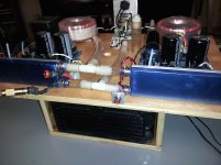
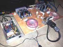
IT"S ALIVE
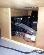
Bomac Liquid Audio has passed beta. A fun project I've been thinking about for far too long to admit.
Honestly, I haven't done direct comparisons with air cooled HS and listening tests to see if it is worth the effort. The results are as follows:
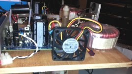
The standard HS settles in at about 115 - 117 F with room temp of 70 F.
After 45 minutes with liquid system active - level of 87 db @ 14':
Left amp - A =90.5, B=80.3, C=72.1
Right amp - A=91.4, B=80.9, C=72.0
After reducing the level to 76 bd for 30 minutes:
Left amp - A=83, B=74.3, C=69.0
Right amp - A=81.6, B=72.2, C=68.0
The most obvious is the A/B gap. I attribute that to the use of heat transfer tape as opposed to a thin layer of paste. Not sure why one side is cooler than the other with the tee configuration.
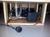
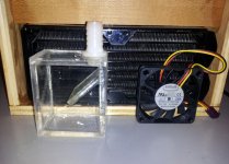
The pump is absolutely silent but the fans are not:
@ 2" = 60db
@ 4' = 51db
@ 14' = too low for meter to read
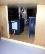
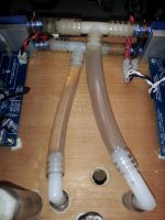
I don't consider that a big problem as a rheostat on that line can actually provide an improvement. This pump runs full speed, but both fan and pump at lower speed improve heat transfer from the radiator. The options are a single fan, or using the 70mm format as shown in an earlier post. The 70s (complete system) could easily fit in a standard 17" chassis. The fans are standard PC units and much quieter devices are available. This is the radiator used. I built a small reservoir but used the "T-line" to reduce the volume of liquid.
I'll play with it more next week, but I think there is a useful potential for adventurous builders.
Bomac Liquid Audio has passed beta.
A fun project I've been thinking about for far too long to admit.Honestly, I haven't done direct comparisons with air cooled HS and listening tests to see if it is worth the effort. The results are as follows:
The standard HS settles in at about 115 - 117 F with room temp of 70 F.
After 45 minutes with liquid system active - level of 87 db @ 14':
Left amp - A =90.5, B=80.3, C=72.1
Right amp - A=91.4, B=80.9, C=72.0
After reducing the level to 76 bd for 30 minutes:
Left amp - A=83, B=74.3, C=69.0
Right amp - A=81.6, B=72.2, C=68.0
The most obvious is the A/B gap. I attribute that to the use of heat transfer tape as opposed to a thin layer of paste. Not sure why one side is cooler than the other with the tee configuration.
The pump is absolutely silent but the fans are not:
@ 2" = 60db
@ 4' = 51db
@ 14' = too low for meter to read
I don't consider that a big problem as a rheostat on that line can actually provide an improvement. This pump runs full speed, but both fan and pump at lower speed improve heat transfer from the radiator. The options are a single fan, or using the 70mm format as shown in an earlier post. The 70s (complete system) could easily fit in a standard 17" chassis. The fans are standard PC units and much quieter devices are available. This is the radiator used. I built a small reservoir but used the "T-line" to reduce the volume of liquid.
I'll play with it more next week, but I think there is a useful potential for adventurous builders.
Attachments
Actually, I don't have a clue
That is what the whole experiment is intended to discover. Paraphrasing Andrew from an earlier dialog - a chip will function best when most distant from both its temperature and electronic self-protection triggers. This just caries that concept to the extreme.
I suspect if there is a sonic benefit it will only appear at high volume levels and/or in a situation where the FE is driven with a gain device like the JC-2 preamp. Conventional air flow cooling has been sufficient with properly built amps. (Though I have been thinking about us taking up a collection to buy Mr. Inserra something more presentable )
Since this is experimentation week I'm going to try to get the Visual Analyzer software up and running to go along with listening tests. Liquid cooling works well in eliminating noise and helps when "over-clocking" PCs. Whether there is any similar benefit for amps is to me, unknown at this time.
That is what the whole experiment is intended to discover. Paraphrasing Andrew from an earlier dialog - a chip will function best when most distant from both its temperature and electronic self-protection triggers. This just caries that concept to the extreme.
I suspect if there is a sonic benefit it will only appear at high volume levels and/or in a situation where the FE is driven with a gain device like the JC-2 preamp. Conventional air flow cooling has been sufficient with properly built amps. (Though I have been thinking about us taking up a collection to buy Mr. Inserra something more presentable
)Since this is experimentation week I'm going to try to get the Visual Analyzer software up and running to go along with listening tests. Liquid cooling works well in eliminating noise and helps when "over-clocking" PCs. Whether there is any similar benefit for amps is to me, unknown at this time.
Last edited:
I Humbly Apologize for my Mistakes
Consider this an official withdrawl of all measurements and comments in post #355.
First there was the helpful critique from Bill and Andrew, followed by some calibration work and comparison of the software measurement tool, an attempt at my Dad's old oscilloscope, and measurement with my DVOM. Basically, I have concluded that I am picking up noise somewhere other than the FE's when using the software tool. The oscilloscope comes closer to the measurements of the DVOM, but it has a noise floor which is a bit high to be useful. Assuming the DVOM measurement with the input shorted to be OK, then the good hum performance that I hear is backed up by that measure.
Boy, this measurement stuff is hard.
Jac
Jac, you're not alone. In my last post I mentioned a promising software called Visual Analyzer. Come to find out the supporting thread on this forum stopped in July due to problems similar to what you describe and have experienced.  I'm as anxious as you to gain some knowledge and experience with measurements, but it appears not as easy as one would hope.
You are to be commended for your efforts and encouraged to continue the quest.
I'm as anxious as you to gain some knowledge and experience with measurements, but it appears not as easy as one would hope.You are to be commended for your efforts and encouraged to continue the quest.
Last edited:
Though I have been thinking about us taking up a collection to buy Mr. Inserra something more presentable
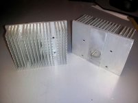
I agree with you on Dario's interesting looking heatsink. I think he spent all his money on the R-core transformers and didn't have any left for heatsinks.
Those silly aluminum plates are, actually, hard disk heatsinks from an old Fujitsu-Siemens server...
Ok, Ok.
I'll finally buy a case for the amp...
BTW the R-Cores were buyed 3 years ago... the big expense for the FE has been for all the alternate parts...

finally fixed the problem with the grounding noise, now the board is dead silent!
the cause was one of the smd resistors (replaced them all).
So there are actually one thing is left to be solved - very poor bass reproduction. The speakers are ASW Genius 100, quite big for bookshelves and connected to my Restek make me feel the bass with my guts. FE sounds opposite - everything below 70-80hz is cut I would say.
Tried replacing 1uf Russian cap with 2x0.47uf Wima mkp - no difference at all. Then I had an assumption that smth could be wrong with these big 15y old Philips cap in PS, replaced them with 2x2200uf BC per rail (know it's not enought, but all I had) - again same bass I felt. As for C9, tried Tonerex, FC, MUSE - same picture.
So I feel really desperate now, don't know what else to check... Any guess or piece of advice would be very appreciated
I'll try later swapping my reverse C9 R10 configuration and playing with R13 (also Takman).
found no difference here as well regarding the bass issue I have
hi Bob,
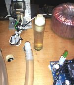
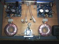
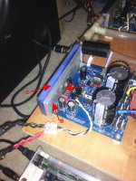
some pics are here, but will make more close ones later.
R10, R13 - Takman
R3 -2x 1R Dale 1%
D4 -1N5819 SCHOTTKY
C10 - 22pf Silve Mica
C30,32,12 - Amstar
R11 - Vishay 1%, 0.6W 1R
1uf cap is K71-4
C16 (Tonerex), C15 (Silmic)
other resistors on top are Vishay 1%
for 0.1% smd Rs I used Panasonic
Not sure about the heat, could be or could be another mistake in the shop as I've already reported several pages earlier when I had a relay issue where R2 was 100 or 1000 times less than in should be. Will be more careful and check every component I buy from now.
Regarding the bass issue forgot to say that R10 & R13 were swapped with Vishay 1% metal film resistors to be sure that the cause is not in Takman. Anyway I was unlucky again. Different directions also didn't make any bass changes.
- Status
- This old topic is closed. If you want to reopen this topic, contact a moderator using the "Report Post" button.
- Home
- Amplifiers
- Chip Amps
- My_Ref Fremen Edition RC - Build thread