Since we are talking about wires, I'll sneak in an off topic post and not feel quite as guilty. I have been looking at these for over a year but didn't want to get bitten by the snake oil monster .
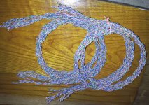
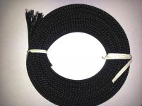
DIY Cat5 Speaker Cables
The cost is low and the time necessary is mostly free, so I spent the better part of three days this week twisting wires and fingers. IMO, it was well worth the effort. The biggest impressions are an enhanced 3D effect and very clear , defined and controlled bass. Lots of slam when it is called for.
I won't hijack the thread but will add a link to the post on the speaker thread when I get it there.
Very nice with the FE amps. Could have used that solder pot on the ends !!
I have been looking at these for over a year but didn't want to get bitten by the snake oil monster .DIY Cat5 Speaker Cables
The cost is low and the time necessary is mostly free, so I spent the better part of three days this week twisting wires and fingers. IMO, it was well worth the effort. The biggest impressions are an enhanced 3D effect and very clear , defined and controlled bass. Lots of slam when it is called for.
I won't hijack the thread but will add a link to the post on the speaker thread when I get it there.
Very nice with the FE amps. Could have used that solder pot on the ends !!
Attachments
Last edited:
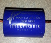
Regarding litz leads of True Copper's: I used fine sandpaper to remove the insulation from the end of each individual litz wire after untwisting the ends. Took about 30 minutes per cap. Soldered just fine after that. Even with short leads, there was very little or no heat to the cap. I'd be very careful with these.
What proved to be a bigger concern for me was fitting the huge wires into PCB holes. I added a very short pigtail of fine gauge OCC solid copper to the lead. I hate adding another connection, but I had no choice, other than cutting a couple of the litz wires to make the lead smaller. I'm not sure what effect that would have.
I guess these caps are built for crossover duty, not coupling. We may be pioneers!
Bob, what value cap would you be getting in your potential group buy? Sounds like a great idea.
Those speaker cables are insane. Do us all a favor and insulate the spade lugs before two accidentally touch and ruin your amp.
Peace,
Tom E
Last edited:
Did anyone of you knows how well this litz wire can be cleaned and soldered using an aspirine tablet ?
Put the wire on top of an aspirin tablet and apply a well-tinned soldering iron. The insulation will come off after the aspirin melts and the wire will be nicely tinned. Be aware the resulted gas is very iritating.
Put the wire on top of an aspirin tablet and apply a well-tinned soldering iron. The insulation will come off after the aspirin melts and the wire will be nicely tinned. Be aware the resulted gas is very iritating.
Last edited:
Hi Tom,
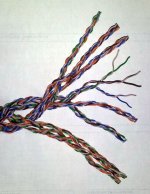
After reading the wiki it appears the braid on the speaker cables can be thought of as an exaggerated application of the litz principal. That begs the question - Would there be an advantage in using litz between the FE and its chassis mounted in/out sockets? Don't know. Dario's video link shows a giant bulk reel.
The cable photos show a temporary setup - done with caution. I have two versions of the Sunflower crossover. I'm using the original because the revised new one doesn't yet produce the correct timbre in the high spectrum where jazz trumpets are heard. I am in a dialog with Ken at Sonicraft in pursuit of a solution. His suggestion (guaranteed he says) is substituting some Jupiter Vintage Flat Stack caps - the total for my needs approaching $400. To my surprise, moving from a toroid to an R-core in my Mini 2496 DAC build produced the best trumpet sound I have heard. (BTW: the XO eventually will be mounted inside the woofer cabinet using a bi-amp capable plate. Humm - Maybe 4 EFs ???)
I'm reporting all of this here for a couple reasons. As with the True Coppers, there appears to be a valid case for blending between the world of high end crossover parts and those normally associated with amp building - ex. soongsc's question here. It will also be interesting to hear from RC builders who have the ability to compare toroids vs R-core transformers supplying the Fremen Edition.
The caps in the quote request were 1.2 uF 630 VDC as you recommended originally. Do you recommend trying other values? I know many are hesitant to shell out that much money, and maybe you could report (or post a link) here informing FE builders of how you made this great discovery and what alternatives you tried.
Dario suggested that a U.S. group buy for the solder pot might be in order. I'll be happy to organize that also if there is some interest.
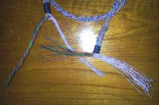
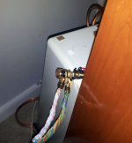
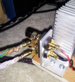
P.S. The ends of the speaker cable are temporary. You can see the barrel at the amp end is too small to fit over the bundle of wires and have to be replaced. Had to solder the bundle and file down to what would fit - kind of like your problem fitting the TC leads. I also ran out of high quality solder. When I get what I need the ends will be redone with insulation and the entire cable covered with nylon mesh. Additionally, on the other extreme, last weekend I tried some "Euro Style" single strand Radio Shack 30 ga magnet wire for cables with surprisingly good results from mids up. Really impressive stage and definition.
After reading the wiki it appears the braid on the speaker cables can be thought of as an exaggerated application of the litz principal. That begs the question - Would there be an advantage in using litz between the FE and its chassis mounted in/out sockets? Don't know. Dario's video link shows a giant bulk reel.
The cable photos show a temporary setup - done with caution. I have two versions of the Sunflower crossover. I'm using the original because the revised new one doesn't yet produce the correct timbre in the high spectrum where jazz trumpets are heard. I am in a dialog with Ken at Sonicraft in pursuit of a solution. His suggestion (guaranteed he says) is substituting some Jupiter Vintage Flat Stack caps - the total for my needs approaching $400. To my surprise, moving from a toroid to an R-core in my Mini 2496 DAC build produced the best trumpet sound I have heard. (BTW: the XO eventually will be mounted inside the woofer cabinet using a bi-amp capable plate. Humm - Maybe 4 EFs ???
)I'm reporting all of this here for a couple reasons. As with the True Coppers, there appears to be a valid case for blending between the world of high end crossover parts and those normally associated with amp building - ex. soongsc's question here. It will also be interesting to hear from RC builders who have the ability to compare toroids vs R-core transformers supplying the Fremen Edition.
The caps in the quote request were 1.2 uF 630 VDC as you recommended originally. Do you recommend trying other values? I know many are hesitant to shell out that much money, and maybe you could report (or post a link) here informing FE builders of how you made this great discovery and what alternatives you tried.
Dario suggested that a U.S. group buy for the solder pot might be in order. I'll be happy to organize that also if there is some interest.
P.S. The ends of the speaker cable are temporary. You can see the barrel at the amp end is too small to fit over the bundle of wires and have to be replaced. Had to solder the bundle and file down to what would fit - kind of like your problem fitting the TC leads. I also ran out of high quality solder. When I get what I need the ends will be redone with insulation and the entire cable covered with nylon mesh. Additionally, on the other extreme, last weekend I tried some "Euro Style" single strand Radio Shack 30 ga magnet wire for cables with surprisingly good results from mids up. Really impressive stage and definition.
Attachments
Last edited:
What proved to be a bigger concern for me was fitting the huge wires into PCB holes.
In the RC boards the holes are large enough by design.
Dario suggested that a U.S. group buy for the solder pot might be in order. I'll be happy to organize that also if there is some interest.
Maybe it's not clear... what I've suggested it's not a solder pot for each partecipant but a single one to be shared among them.
That's a possibility. Using the smallest box (click -> "more"on selection) is $5.35 to move it around. What are the dimensions?
Postage Price Calculator
Postage Price Calculator
A single solder pot paid for by the group buyers and the group receiver pre-tins all the cap leads before sending them out to the buyers.
Then decide who gets to keep the solder pot (DIYaudio).
Exactly
Inviato dal mio LT22i con Tapatalk 2
Hey Andrew, good to hear from you. Hope your vaca was enjoyable. We are expecting a travel log video post soon.
Builders - pleas send a PM if you are interested - even if you don't plan to buy the True Copper caps at present. That way we can determine the need to pursue this path.
Builders - pleas send a PM if you are interested - even if you don't plan to buy the True Copper caps at present. That way we can determine the need to pursue this path.
Do you guys try to wash off the tacky flux after soldering? They say you don't have to, but there is more flux left than usual.
If you do remove the flux, do you wait until all components are soldered? My though is alcohol and a toothbrush, but I am very open to suggestions.
Jac
If you do remove the flux, do you wait until all components are soldered? My though is alcohol and a toothbrush, but I am very open to suggestions.
Jac
Here's my process. I do it after soldering is done and keep the top dry.
http://www.diyaudio.com/forums/anal...a-pre-myref-fe-integration-5.html#post3068356
http://www.diyaudio.com/forums/anal...a-pre-myref-fe-integration-5.html#post3068356
Do you guys try to wash off the tacky flux after soldering?
Absolutely
If you do remove the flux, do you wait until all components are soldered?
It makes sense.
I usually clean two times, the first after SMD soldering and the second after TH soldering.
My though is alcohol and a toothbrush, but I am very open to suggestions.
I'm using a specific spray with its brush but I guess that alcohol and a toothbrush will do.
Another build note. For D4, the Vishay 1N4001 diodes that I bought in the US from Mouser had thick leads. These leads are so thick that they have to be forced through the hole in the board and shave off a little material from the leads along the way.
The next time boards are made, it would be nice if the hole in the board were slightly larger diameter. I suspect that common components like the 1N4001 have a variety of variables like this.
Jac
The next time boards are made, it would be nice if the hole in the board were slightly larger diameter. I suspect that common components like the 1N4001 have a variety of variables like this.
Jac
A little more on the D4 leads.
If you get the same parts as I did, the hole fit will be tight enough that solder won't flow into the hole. I wanted to be sure that I didn't damage the continuity between the top and bottom of the board by scrapping off some of the hole plating, so I soldered the leads on both top and bottom. Thanks to Dario, there are nice solder pads on both sides.
Jac
For D4, the Vishay 1N4001 diodes that I bought in the US from Mouser had thick leads. These leads are so thick that they have to be forced through the hole in the board and shave off a little material from the leads along the way.
Hi Jac,
yes diodes' holes are a bit too much tight.
For a more confortable fit leads must be bent with care so that the distance between them is exactly the same of holes.
If you get the same parts as I did, the hole fit will be tight enough that solder won't flow into the hole. I wanted to be sure that I didn't damage the continuity between the top and bottom of the board by scrapping off some of the hole plating, so I soldered the leads on both top and bottom.
This is not necessary, the hole plating is strong...if you have doubts simply measure continuity with the multimeter.
Soldering on both sides will result in a much more difficult to remove component in case you need to do some repair job.
The next time boards are made, it would be nice if the hole in the board were slightly larger diameter.
Yes, I've updated Eagle files after the first build on green boards.
Yesterday, I started soldering to board (Thanks Dario for the excellent built of the board and help with the smd parts). I swore that those little smd buggers are alive. They just love to jump like ticks. I got lucky twice with the help of my kids to look for it (They jump out as soon as I open up the packgaging carefully). Looking forward to finish at least a channel by next week.

- Status
- This old topic is closed. If you want to reopen this topic, contact a moderator using the "Report Post" button.
- Home
- Amplifiers
- Chip Amps
- My_Ref Fremen Edition RC - Build thread