First power up
After branching transformers you can fire up modules (be sure they're heatsinked....") ) with all inputs and outputs disconnected.
) with all inputs and outputs disconnected.
You should hear relais click, this is the first good news, it means modules are working and no serious DC is present at output.
Keeping modules powered on we then proceed to measure DC offset at output tabs.
It should measures less then 20mV and with shorted inputs less then 10mV.
If relais don't click don't panic, power off modules and ask help on this thread.
 Disclaimer
This tutorial it's not the unique way to build the amp and it's not necessarily the best one but it worked for me several times.
After branching transformers you can fire up modules (be sure they're heatsinked....
) with all inputs and outputs disconnected.You should hear relais click, this is the first good news, it means modules are working and no serious DC is present at output.
Keeping modules powered on we then proceed to measure DC offset at output tabs.
It should measures less then 20mV and with shorted inputs less then 10mV.
If relais don't click don't panic, power off modules and ask help on this thread.
DisclaimerThis tutorial it's not the unique way to build the amp and it's not necessarily the best one but it worked for me several times.
My only suggestion so far is to go through the tutorial several times before starting the build. This morning I sent Dario a PM questioning the "thermals" reference in post #10. He referred me back to post #7 where I had completely blown past the explanation. So be attentive. Don't hesitate to post problems and questions.
I also had mentioned the need for some pre-planning if builders think they will mount the LED on a front panel. Dario made note of that in the thread.
Will read through again tonight, but I can't imagine a more thorough and detailed guide.
It's gonna be great fun and rewarding!
Don't hesitate to post problems and questions. I also had mentioned the need for some pre-planning if builders think they will mount the LED on a front panel. Dario made note of that in the thread.
Will read through again tonight, but I can't imagine a more thorough and detailed guide.
It's gonna be great fun and rewarding!
Dario,
If I may suggest, this would be a good time to lay out the alternative build choices in one place;
Optional capacitors
advantage and disadvantage of the C9 - R10 choice
alternative compensation capacitors
orientation of premium parts
That way, everything is together in one place and easy to find.
By the way, the build looks very good.
Jac
Dario,
If I may suggest, this would be a good time to lay out the alternative build choices in one place;
Optional capacitors
advantage and disadvantage of the C9 - R10 choice
alternative compensation capacitors
orientation of premium parts
That way, everything is together in one place and easy to find.
By the way, the build looks very good.
Jac
And a complete list of locations for sockets. this way a builder could lay out the socketed positions ahead of time and not have to worry about trying to remember the swap locations while populating the board. This way no leads get accidentally trimmed.
I have a list that I have been carrying around in my pocket of the locations that I have identified (it is written on a copy of the pcb) but I am sure I missed a spot or added one.
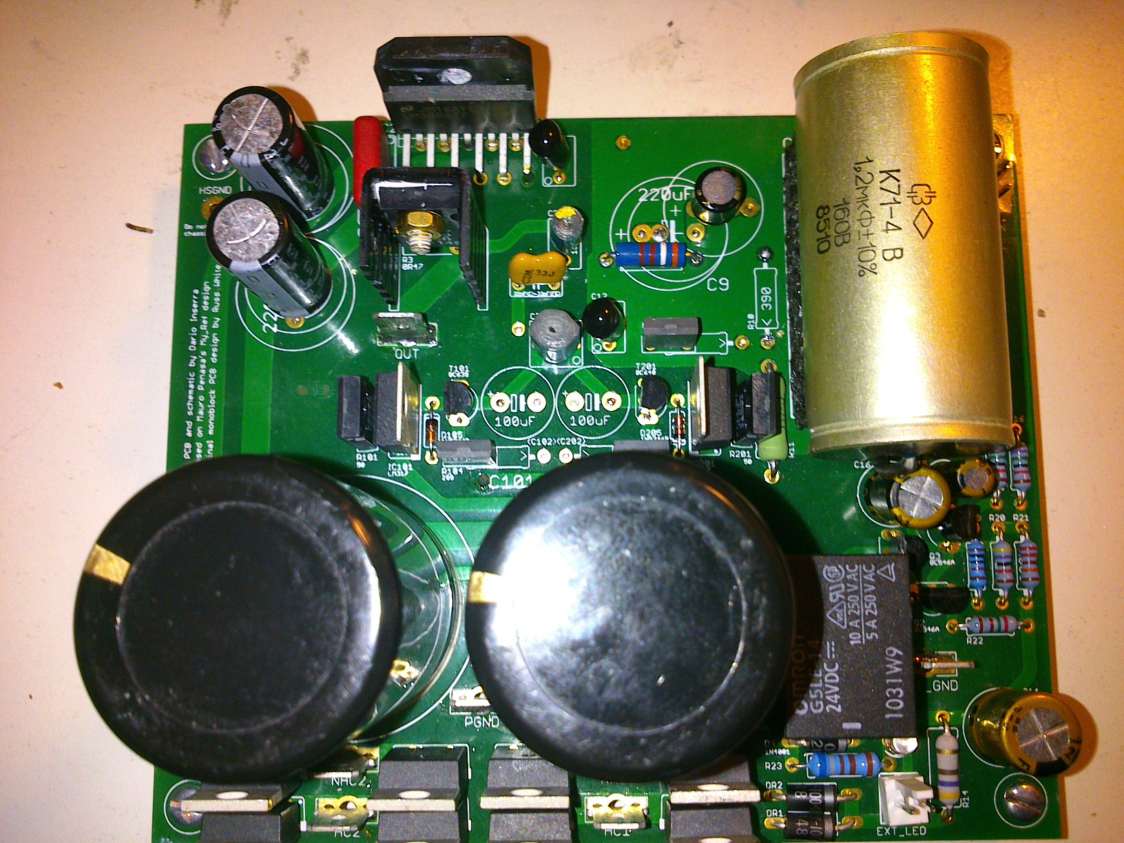
Optional capacitors
Otional capacitors C102/C202 are there just beacuse there was space for them but I wouldn't use them unless stability problems arise.
The amp sound better without.
advantage and disadvantage of the C9 - R10 choice
Functionally both arrangements are identical but the new one makes the circuit less prone to pickup noise.
To my ears it also sound better...
But experimenting with both arrangements is encouraged to confirm the final choice.
alternative compensation capacitors
Rev C compensation is the original one developed by circuit designer Mauro Penasa, it's a no brainer and sounds great.
FE compensation has been 'guessed' by me via trial and listen and sound more refined in the high range with a tighter bass and (much) wider and deeper soundstage, LinuxGuru simulations and several months of use proved it's stable.
FE compensation can be considered experimental but it's the one I suggest to use.
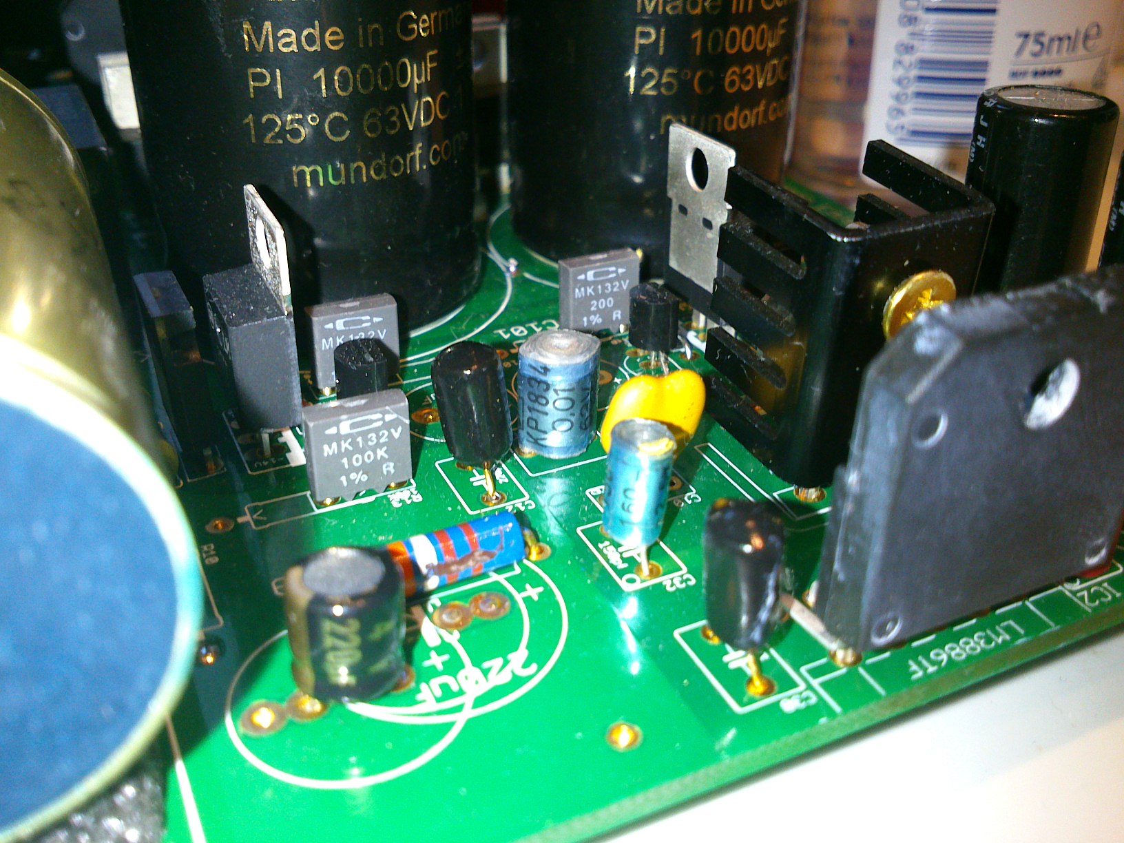
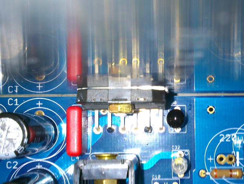
orientation of premium parts
Amtrans are oriented exactly like FKP2s
150pF KP1834 have a yellow mark (see picture)
And a complete list of locations for sockets.
I don't know how much it can be useful since it depends on what you want to experiment with...
BTW
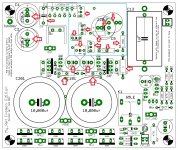
The area in the cyan rectangle is the most interesting to explore.
The positions that should be socketed for sure are C9 and R10 to determine which C9/R10 arrangement it's the best one.
Builders that don't want to experiment are encouraged to use the alternate arrangement
Attachments
Last edited:
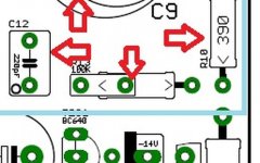
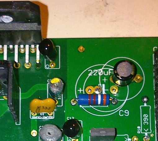
Dario, orientation at R13 appears a bit confusing.
It's because R13 can accept both Mk132 an 0309 resistors.
The left orientation is for Caddocks while the right one is for KOAs.
Inviato dal mio LT22i con Tapatalk 2

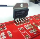
Here is a note on mounting the LM3886 as shown in post #18. This came up back in the MyRef V1.2/V1.3 threads. Minor alignment problems can be corrected by insuring there is a little stand-off from the board. When making measurements to locate where to drill the hole in the heatsink, a spacer like a matchstick or toothpick will ensure there is some flexibility on the pins - which need to protrude completely through the holes - but horizontal of chip leads should not be flush to the PCB.
Having the standoffs mounted at this step is important. Also try to think about the need for any clearance between the bottom of the heatsink (if needed) and the chassis that will house the amp. Spacers may be useful here also. Dry/cold fit everything before drilling and/or applying solder.
Having the standoffs mounted at this step is important. Also try to think about the need for any clearance between the bottom of the heatsink (if needed) and the chassis that will house the amp. Spacers may be useful here also. Dry/cold fit everything before drilling and/or applying solder.
Attachments
Last edited:
The LM3886 Eagle component I've used in RC boards it's a new one derived from National one, different from all previous, and have exact holes.
It will be easier to desolder the part if needed and LM3886 will slide in without alignment problems.
For the same reason the LM3886 will no more stand up without soldering like in Bob's pictures.
Also I've aligned component so that the LM3886 edge will have at least half millimeter from board's edge so that it should adehere perfectly to heatsink.
To those of you who used a board (non-conducting chassis) as a test chassis, what did you do regarding PGND? Did you connect PGND to mains ground?
Hi Jac,
like in the Evolution Rev A I've left PGND not connected.
In my case the amp sound worse with PGND connected to safety ground.
In this moment only transformers' shield is connected to safety ground; when it will be cased also the chassis will be connected to safety ground.
I'm pretty sure that grounding will be one of the more discussed topics in this thread...
The newer Antek toroids have a "shield" wire that I have connected to safety ground. It doesn't pass through to the amp. The older "standard" toroids and the ApexJr pieces don't have that feature. Just bought my first R-core for a DAC and it has a safety ground also - as noted above by Dario - again tied back to the AC inlet.
I see the shock hazard to be greatest from the power inlet to the trani. Good insulation and lots of heat shrink tubing can deal with that - IMO. The reduced AC voltages from trani to the amp I believe are less of a threat, but even that leg can be well protected from physical contact.
So I guess the two remaining issues are protection of some board components, and how safety ground effects the sound. Does that sound correct? I'm not sure if something like a CL-60 would be beneficial here. I have seen Siva recommend it's use on several threads.
Last edited:
Boards up and running
I've finished my build, both boards are playing music in this moment

I've had some trouble with one module though...
It power up correctly, relay was clicking but it was mute....
Guess what was the cause?
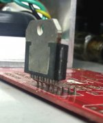
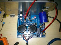
An interesting demonstration
As you can see, thanks to the new eagle object and positioning, there is clearance between board and heatsink.
I've finished my build, both boards are playing music in this moment
I've had some trouble with one module though...
It power up correctly, relay was clicking but it was mute....
Guess what was the cause?
An interesting demonstration
As you can see, thanks to the new eagle object and positioning, there is clearance between board and heatsink.
Attachments

I was forgotting DC offset measurements:
6.4mV and 5.8mV
Only thermal compound
6.4mV and 5.8mV
Dario, are you isolating the ic from the heatsink with anything but the thermal compound? It is hard to tell from the last pic.
Only thermal compound
Some addititional notes for builders
For those that bought the ERO kit
Solder the KP1834s as the last parts, after cleaning the boards.
Polystirene is very delicate and I can't find a datasheet to confirm or not they can stand with solvent washing.
Soldering temperature for C101/C201
The thermal pads of both caps need a very high temperature to be be well soldered, I would say around 370-380 °C.
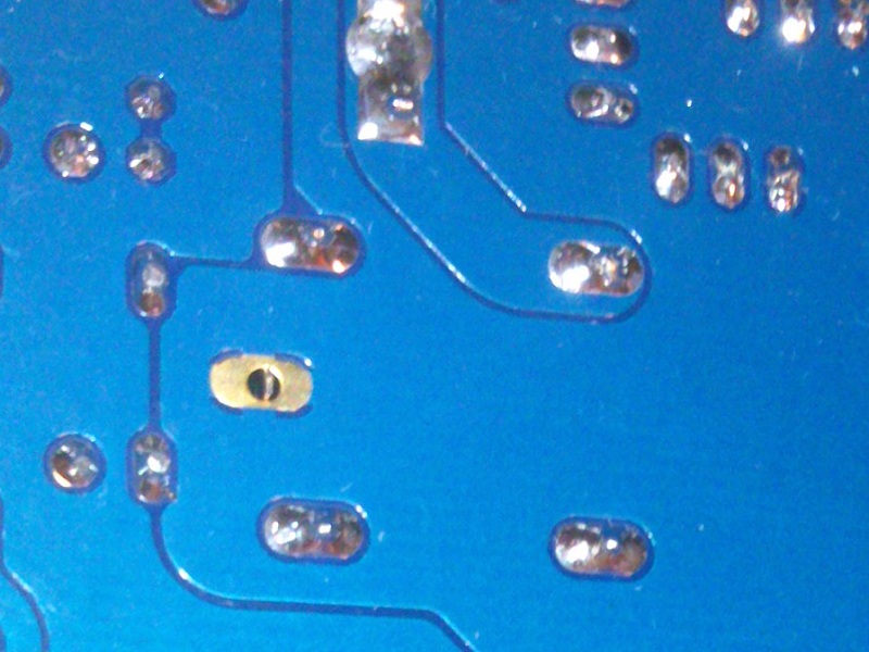
Final inspection before powering up
Before powering up inspect all solder joints surrounded by the groundplane to insure joints are exactly on pads without making bridges with the groundplane.
It shouldn't be a problem thanks to the soldermask but it's a cleaner and safer job.
For those that bought the ERO kit
Solder the KP1834s as the last parts, after cleaning the boards.
Polystirene is very delicate and I can't find a datasheet to confirm or not they can stand with solvent washing.
Soldering temperature for C101/C201
The thermal pads of both caps need a very high temperature to be be well soldered, I would say around 370-380 °C.
Final inspection before powering up
Before powering up inspect all solder joints surrounded by the groundplane to insure joints are exactly on pads without making bridges with the groundplane.
It shouldn't be a problem thanks to the soldermask but it's a cleaner and safer job.
- Status
- This old topic is closed. If you want to reopen this topic, contact a moderator using the "Report Post" button.
- Home
- Amplifiers
- Chip Amps
- My_Ref Fremen Edition RC - Build thread