Why is the schematic supplying 31V to the relay circuit? Does a 24V relay need that much overdrive to pull in quickly?
Does the slow build up of charge (~1.2V) across C16 via current fed from 220k allow a fast trip of the relay? Or will the relay coil current increase until the solenoid thinks it's time to pull over and then the supply rail gets a big glitch and the charge on C16 drops and the relay releases. A stupid design. All three modified versions of my MyRef worked first time and every time Even though a reply to my post suggested I was daft to even contemplate changing the schematic. MyRef was a terrible implementation. This one is just as bad.
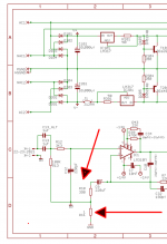
Andrew,
I agree with your overall assessment of how the system works. I have a simulation running in an old copy of Electronics Workbench which has a nice relay model. It is as you suggest. If the relay didn't close, the circuit that is labeled +24V to the relay, would climb to full positive rail voltage, about 31 V. R14 (combined with the relay, R21, and R22) also controls the voltage across the relay when the transistors conduct and the relay closes. When the relay is closed, the voltage drops to somewhere between 12 and 24 V as indicated on the schematic.
I agree that your snap action capacitor would add some energy to closing the relay. In my case, I haven't added the capacitor yet because the relay system has been perfectly reliable. It is on my list.
Badrisuper,
I don't know the source of your problem. If the transistors conduct to ground, the voltage on the plus side of the relay will climbing to more than 30 V to close the relay. That shouldn't be the problem. It is likely that there is another reason which is keeping the transistors from conducting. I would suggest measuring the voltage on the other side of the relay, for example, measure DC voltage opposite the "stripe" on D4 to ground. If the relay is not closing, the voltage will be almost the same on both sides of D4 (about 30V). That means that the transistors aren't conducting and probably indicates DC voltage in the output of the amp. Either that or a connection or component problem downstream from the relay.
Good luck.
Jac
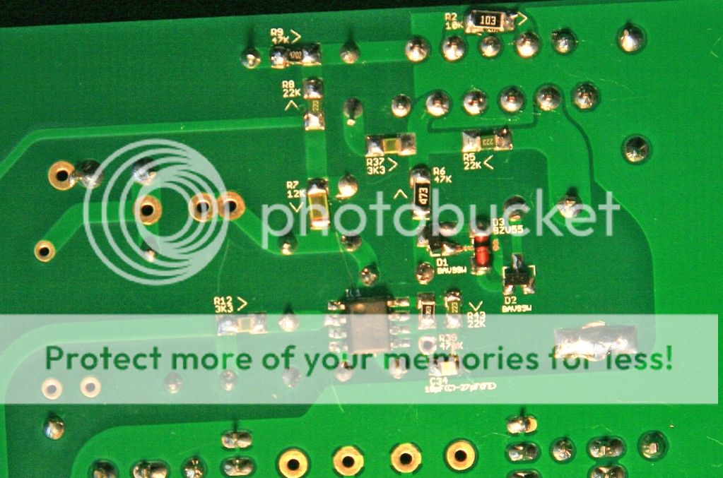
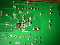
At a quick glance, D1 looks like there is a possibility of overhearing at install. If you look at the schematic it is at the heart of the problem area you describe. The pad just below that also looks suspect - may just be photo. What is the condition of the bottom trace from D1 to the middle of D3?
D3 is not same in appearance. Is that the corret value? That piece on my build is from the Mouser BOM
.
D3 is not same in appearance. Is that the corret value? That piece on my build is from the Mouser BOM
.
Attachments
Last edited:
Full schematic is public at google docs page.
Attachments
Hi,
Last day I blown the R11 resistor. Today I replaced a new one. But now audio is coming from one board and not from the other. LM3886 in the other getting too hot. Can anyone tell what would be the cause?
Thanks
Badri
Not clear- are you saying you have one fully working board or different problems on both boards/PCBs?
For some reason the solder mask came of in that area.
Were you able to repair that trace and confirm full continuity?
Not clear- are you saying you have one fully working board or different problems on both boards/PCBs?
I have one fully working board. But another no sound. The faulty one's LM3886 getting too hot.
Thanks
Badri
Badri, Unfortunately it appears you will have to take the same path as Marra. The voltages are the clearest method to solving problems. The schematic is linked a few posts back, and if you have difficulties knowing where to place the probes - please post and someone will help.
Just checked a few things both p/s are giving +-30v with +- 14.6v on C102/202 on the good board? but +13.91 and -14.6v on the other.Also on the good one D3 has 2v across it whereas the other has 29v. When powered off the led lights momentarily after 10 or so seconds but the relay no longer clicks on/off.
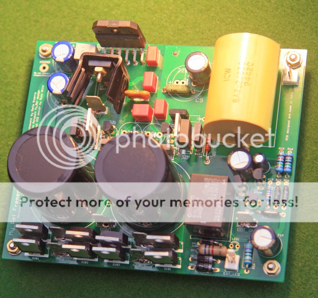
Finally some pics
Some SMD soldering is suspect... particularly R6.
In general it seem too much solder has been used (did you use flux?).
R7, R12, R17 seem to have no markings, are you sure about their values?
You can completely remove the diode limiter (D1, D2, D3) for test, the amp works also without it, it's a safety circuit.
Dario thanks for the response;flux was used;guess I overoaded the soldering iron tip.The three resistors are the correct values but are Vishay thin film.I should have asked Bob to get me some Susumas when he very kindly supplied some other items I could'nt get from Farnell.
I will remove the diodes and see what happens.What voltage reading should I be getting across there?

- Status
- This old topic is closed. If you want to reopen this topic, contact a moderator using the "Report Post" button.
- Home
- Amplifiers
- Chip Amps
- My_Ref Fremen Edition RC - Build thread