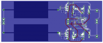
Please criticize my work! I am a beginner in electronics and PCB routing. This is basically PIMETA1 and PIMETA2 copy. Had hell of a struggle routing PCB... First I tried to manage with one layer, but then had to add a bunch of jumpers which made it ugly and confusing. Now it's double side, but still I have some doubts with my VCC routs.
P.S. Bypass capacitors tantalium and X7R, signal input capacitor 1uF 630V AMPOHM FP-CA-AU (they are biG compared to whole PCB).
Critics are needed!
P.S. Bypass capacitors tantalium and X7R, signal input capacitor 1uF 630V AMPOHM FP-CA-AU (they are biG compared to whole PCB).
Critics are needed!
Attachments
You are missing resistors (reference to ground) on both opamps noninverting inputs. What is the gain around input opamps (inner feedback loop)? Output dc servo will not work as you will have different dc offset at each output. You have to add some electrolitics at BUF64 power supply pins 'cos they form power ground point for each channel.
you don't have any DC bias current path input the OPA627 +in, fets don't need much bias current but its still more than zero
are you driving from a low Z source or a volume pot?
the OPA627 is one of the best op amps on input common mode impedance linearity - less need to balance the +/- input source/feedback Z
balancing can't be done with classic stereo pot input because the source Z varies with volume setting
I know in great detail where the "inner loop" feedback, flawed reasoning comes from - it doesn't do what the proponents think - Walt Jung later agreed that high loop gain feedback amps can be made with low TIM/PIM and Otala's "flat loop gain over audio" prescription was unnecessary
You can safely omit R3,4
the ccs loads can be made simpler - neither the BUF634 or OPA627 swings close enough to the rail to justify the low operating V of the mirror css
and the output should have some series Z to isolate the amp from excessive cable C loading which can destabilize the loop by adding phase shift when interacting with the BUF634 ~ 5-10 Ohm output Z
the mentioned electrolytic bypass for the BUF634 is OK but the board is so small there's little need for multiple electros unless you add isolating L, R or C-multiplier sub regulation to separate the OPA627 supply from the BUF supply
Last edited:
Thank you for your response. Because everything is new to me I have some questions.
*The missing resistors for non-inverting inputs are for balancing impedance of both inputs, yes? (because ideal op amp should have potential difference equal to 0V?)
*Maybe I it would be a good idea to put small potentiometers on opa627 Offset Trim pins? P.S. I will feed preamp from 50kOmh alps pot.
*Considering this type of configuration isn't my feedback loop made from R4(Rf) and R3,2(as Rg)? But R5,3 and R2 also looks like a feedback loop... can someone please explain me a bit?") If I omit R3 and R4 my loop would be R5(Rf) and R2(Rg)?
If I omit R3 and R4 my loop would be R5(Rf) and R2(Rg)?
*Also will put some 10uF tantalium bypass caps for buf634.
*So and on the output after feedback loop I should put a small resistor? like (>50Omh)
Sorry still a learner
*The missing resistors for non-inverting inputs are for balancing impedance of both inputs, yes? (because ideal op amp should have potential difference equal to 0V?)
*Maybe I it would be a good idea to put small potentiometers on opa627 Offset Trim pins? P.S. I will feed preamp from 50kOmh alps pot.
*Considering this type of configuration isn't my feedback loop made from R4(Rf) and R3,2(as Rg)? But R5,3 and R2 also looks like a feedback loop... can someone please explain me a bit?
If I omit R3 and R4 my loop would be R5(Rf) and R2(Rg)?*Also will put some 10uF tantalium bypass caps for buf634.
*So and on the output after feedback loop I should put a small resistor? like (>50Omh)
Sorry still a learner
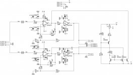
you have a version of Walt Jung's multiloop feedback from his "Op Amp Audio" articles in Electronic Design magazine
the articles attempted to deal with subtle, 2nd order effects beyond basic op amp application
matching the input impedance nonlinearity for jfet input op amps to minimize audio distortion numbers already approaching -80 dB is very "2nd order"
output buffering to unload the op amp, increases the composite amplifier's linearity
the "multiloop" feedback can be considered inherent in a op amp + buffer circuit since the buffer amp also has (built in) feedback determining its (unity) gain
and you have the global or outer loop feedback determining the composite amp gain
R5, R2 define the "global" feedback gain, the feedback divider for the "outer loop"
C1 || R4, R3 define a extra "inner loop" feedback around the OPA627
much has been written by fanboys about the role of in "inner" feedback loop - much of it on Headwize, head-fi forums is wrong
Walt Jung later conceded Otala's PIM idea/"flat loop gain" prescription leading him to try it was not always applicable - in this circuit the "inner" feedback doesn't change the conditions for input gm nonlinearity PIM generation and is rather pointless
R3,4 are simply not needed, remove R4, short R3
C1 probably isn't necessary with the given circuit components and gain but if you change op amps, lower the gain it may needed to assure stability - so I woulkd leave it on the schematic, pcb but not stuff the position, or use a even smaller single digit pF cap to damp the step response
balancing the source, feedback Z seen by the OPA627 +,- inputs is another issue, as long as the + input is driven from a high kOhm volume pot you have a varying source Z with volume setting
since the volume pot source R as seen at the wiper varies from "0" to 12.5 kOhm for a 50kOhm pot you can't match it with a constant R anywhere in the circuit
the simplest “solution” is lowering the source Z by using a lower resistance volume pot – the distortion is porportional to the source impedance
10 kOhms is about the lowest that is available in audio taper, doesn't load what ever circuit that is driving it by too much
Last edited:
- Status
- This old topic is closed. If you want to reopen this topic, contact a moderator using the "Report Post" button.