Hey all -
First post. Wacky topic. Apologies are in order. Possible thread move in the making, but I picked chip amps because my question is rather unique for a diyaudio forum, especially since it combines video along with audio in this case.
The short of it is - I am doing a modification for a video game console. It involves tapping an unused signal for video (YPrPb) and running it out to new RCA jacks. My problem is that I believe I am experiencing some interference due to a simple (bad) choice in wiring.
The project involves pulling a signal off a chip, running it through an NPN transistor (amped with a 5V signal), and running that to an RCA jack. The signal will most likely be terminated at the jack with a 220uf cap and a 75 ohm resistor. The jack is grounded with a 1 kohm resistor.
To create this project, I used your average, radio shack, stranded hook-up wire. I am seeing a very small hint of vertical "bars" of such in the video signal when viewing a solid color, and I can't help but wonder if my problem - and also my weakest link - is my selection for wiring.
Most of the people in this particular hobby are quickly interested in something that "works" and do not focus too much with the quality of their parts, being within spec, or improving upon something that already works. This is why I have come to you guys, as I expect you have a much more fanatic approach to this sort of project.
So getting down to business - What sort of wiring would you recommend I use for the video signal from the chip? For the power (5V)? For the grounding? Can I use shielded Cat-5 for any of this?
I have several additional questions, but I am a fresh member of diyaudio & don't want to push too much via my first post.
Use a 75 ohm resistor inline to the signal, as close to the source (the NPN) as possible. This is your signal termination; at the source side it does not go from signal to ground. Use 75 ohm coax from the resistor to the jacks. Connect the shield of that coax only at the jack end. You should do DC blocking at the jack using a 47 uF (or so) cap inline to the signal (positive end to the NPN, neg to jack center pin) and a 1k to 10k resistor from jack center pin to ground.
Shield is best connected at both ends for EMC.
http://www.bluejeanscable.com/articles/shielding.htm
Also worth looking at stuff by Henry ott and The EMC club.
http://www.hottconsultants.com/
http://www.bluejeanscable.com/articles/shielding.htm
Also worth looking at stuff by Henry ott and The EMC club.
http://www.hottconsultants.com/
I really appreciate these responses and welcome any additional input from you all.
macboy - Does the wire from the chip to the NPN matter? I am using the 30 AWG Kynar - quite an easy solder job when soldering to an SOIC chip, but I can change it if necessary. Following what you wrote, I believe SOIC to jack would be:
1: SOIC -> short, small wire -> transistor (base)
2: Transistor (emitter) -> 75 ohm resistor -> 75 ohm coax -> 47 uf cap -> RCA jack
3: 1k resistor from center pin to ground
I haven't terminated coax before, and my only real experience with it is external. I assume you guys use a much smaller gauge for internal wiring. I am open for recommendations here.
marce - I haven't terminated shielding for coax either way before, so I am cautiously interested in how to terminate that shielding.
macboy - 1k resistor directly from center pin to ground? Do this rather than 1k in parallel from the grounding ring (panel mount RCA jack) to ground?
There is quite a wide variety of uF values used for that last cap. I have heard some say 75 ohm + 220 uF. Some say 110 uF. You mentioned 47 uF. Does the uF value actually make a difference?
johnr66 - I am pulling the 5V from the output of the voltage regulator and going straight to the transistor (collector) using about a 20 AWG hookup wire 75-Ft. UL-Recognized Hookup Wire (20AWG) : Hookup Wiring | RadioShack.com
Would this direct connection without decoupling introduce noise to the video output?
In fact, that hookup wire is what I am currently using for everything aside from the 30 AWG Kynar that goes from the chip to the transistor.
Internally, mini-coax is commonly used. It has higher losses than the thicker kind, but for the short lengths used, that is not a problem. RG179 is one type, if you wanted to seek some out to buy it. But you can salvage some from any (good quality) VGA computer cable, or an S-video cable, since you probably have some of those that aren't being used any more. A short length of kynar wire is probably not a big deal, but it could act as a good antenna, so keep it short. If it proves to be a problem, try replacing it with the mini coax (grounding one end of the shield). Mini coax has a very fine center conductor so it should be easy enough to solder to the SOIC chip.
Use the coax centre for the hot (+) signal and the screen for the return current (0V) for each signal,similar to how you connect composite video externaly:
YPbPr - Wikipedia, the free encyclopedia
These signals are very prone to noise, especially the sychronisation element of the signal, hence the bars. They are high frequency analogue signals and need treating as such, with the utmost care. Digital video is much better.
YPbPr - Wikipedia, the free encyclopedia
These signals are very prone to noise, especially the sychronisation element of the signal, hence the bars. They are high frequency analogue signals and need treating as such, with the utmost care. Digital video is much better.
Thank you again for your responses.
My modification is in a prototyping phase at the moment. Looking at it a bit more, it is quite obvious that it is currently prone to noise.
How does one ground the coax shielding? If I am grounding on one side, I could solder a wire lead from the shielding to the RCA jack's grounding ring. The ring is currently soldered to ground with a 1 kohm resistor in parallel.
I do not have any decoupling caps at the moment. I plan on adding those.
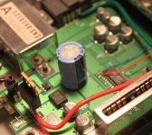
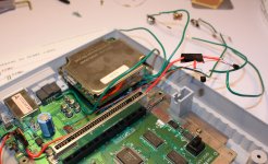
I have posted pictures here to give you an idea of what it looks like in the experimental phase. It is probably obvious why there are light vertical bars visible on the screen when viewing solid colors - You can see that the direct feed of +5V from the power regulator is basically sitting on the (quite long) run of kynar wire from the chip, most of the lines are long, and none of them are shielded.
My modification is in a prototyping phase at the moment. Looking at it a bit more, it is quite obvious that it is currently prone to noise.
How does one ground the coax shielding? If I am grounding on one side, I could solder a wire lead from the shielding to the RCA jack's grounding ring. The ring is currently soldered to ground with a 1 kohm resistor in parallel.
I do not have any decoupling caps at the moment. I plan on adding those.
I have posted pictures here to give you an idea of what it looks like in the experimental phase. It is probably obvious why there are light vertical bars visible on the screen when viewing solid colors - You can see that the direct feed of +5V from the power regulator is basically sitting on the (quite long) run of kynar wire from the chip, most of the lines are long, and none of them are shielded.
Attachments
- Status
- This old topic is closed. If you want to reopen this topic, contact a moderator using the "Report Post" button.
- Home
- Amplifiers
- Chip Amps
- EMI/RF, Proper Internal Wiring for A/V inside a Video Game Console