I've just built my second Carlos FM snubberized LM338 regulated power supply but this time to work with a 30 volt traffo that I had here doing nothing (I used 25 volt traffo last time).
When I completed the regulator circuit, I power it up and everything worked as expected, ie I got the expected voltage from the output. I've used trim pots and was able to vary the voltage by a few volts but settled on 34 volts out from around 42 in.
However, after connecting the supply to the amp and playing for a while ~10 mins (it sounded very good on the test speakers) I checked the voltages again to find that I was getting +/-42 volts instead of +/-34, and both the LM338's had gone short-circuit between the input and output pins.
I've triple-checked the circuit and the actual build but can't find anything wrong. The only two things that I didn't do exactly as CFM's diagram was use .25w resistors for R1 (120R) and R2 (2K7), and to modify the regulator as in the diagram below - which I believe is the correct way to implement these types of regulator to prevent circulating currents.
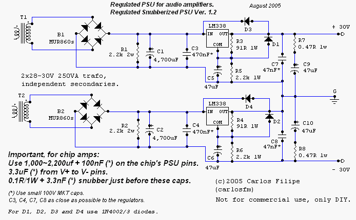
And here is the CFM diagram.
I've done a bit of searching but apart from FastEddy suggesting that the bleeder resistors should be nearer to 10K than 2K2, and also that R1 should be 910R instead of 91R (which I don't understand as the data sheet suggests 120R), I can't find anything to help me.
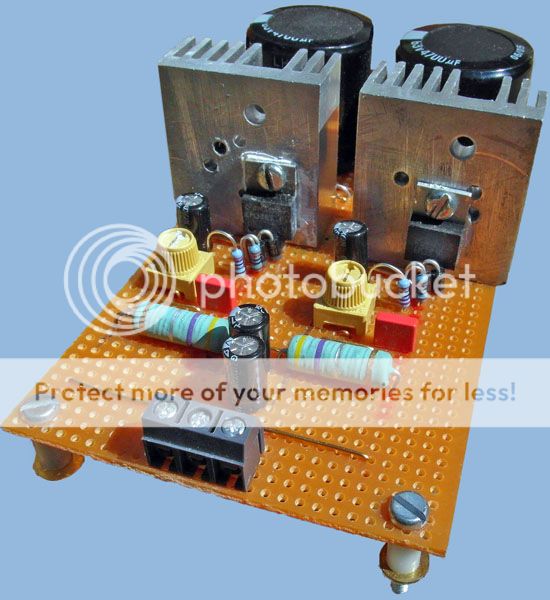
And this is the actual regulator in question. The heat-sinks did get quite hot while playing music.
When I completed the regulator circuit, I power it up and everything worked as expected, ie I got the expected voltage from the output. I've used trim pots and was able to vary the voltage by a few volts but settled on 34 volts out from around 42 in.
However, after connecting the supply to the amp and playing for a while ~10 mins (it sounded very good on the test speakers) I checked the voltages again to find that I was getting +/-42 volts instead of +/-34, and both the LM338's had gone short-circuit between the input and output pins.
I've triple-checked the circuit and the actual build but can't find anything wrong. The only two things that I didn't do exactly as CFM's diagram was use .25w resistors for R1 (120R) and R2 (2K7), and to modify the regulator as in the diagram below - which I believe is the correct way to implement these types of regulator to prevent circulating currents.
And here is the CFM diagram.
I've done a bit of searching but apart from FastEddy suggesting that the bleeder resistors should be nearer to 10K than 2K2, and also that R1 should be 910R instead of 91R (which I don't understand as the data sheet suggests 120R), I can't find anything to help me.
Re: snubbed regulator in your circuit diagram ...
1) I never understood why the value of R1 & R2 was so low in this circuit (2.2K ohms) .... it bleeds off the power supply rails continuously = wasting power and generating heat. (This circuit would fail current production power supply restrictions in Europe and soon, here in the states. = an environmentally incorrect design, etc .... A value about 5 times greater, 10K to 22K ohms would suffice ... or none at all).
2) Likewise, I believe that R3 & R4 should be 910R ohms (instead of 91R ohms) and R5 & R6 should be 22K ohms (instead of 2.2K ohms) ... saving a little more in wasted heat, etc. I would also suggest that for audio work that R3, R4, R5 & R6 be metal film type and held to precision of +/- 2% or +/- 1%. (1/8 watt rating is OK here if R5 & R6 >= 10K.)
3) For capacitors C3, C7, C4 & C8, I would recommend the use of plastic (polystyrene) or comparable "audiophile" quality capacitors ... most especially at C4 & C8. (SoniCaps ?). These capacitors are used here as "snubbing" caps, reacting to and filtering off the higher frequencies and "popcorn" noise associated with fixed voltage regulators and RF from external sources.
4) I always add a Ferrite Bead to the output legs and ground legs of these kinds of linear supplies ... especially if intended for a sperate enclosure. ( Ferrite bead - Wikipedia, the free encyclopedia )
5) Transformer: if independant 30 VAC secondary type is unavailable, then a "center tap", +/- 28 to 30 VAC secondary may be used (although some here might quibble about retaining the "split supply" nature of the original). The center tap can be connected directly to "G" or anywhere upstream of "G" and downstream of the (-) negative LM338 at D2.
6) If output power is expected to exceed ~ 40 watts (output >= 40 VA) ... then a heat sink should be added to both LM338 regulators. If close to the maximum rating of the transformer (200+ VA) then the heat sink(s) on the LM338 should be quite large indeed.
(Alternate part number for LM338 = pin for pin substitution = uA7805, although some here feel that this substitution will be noisier and is of older design.)

And this is the actual regulator in question. The heat-sinks did get quite hot while playing music.
Nick, this is intersting.
When I built my regulated PS's some years ago, I assumed that the heatsinks would get warm, if not quite warm (I just assumed that regulators get warm when regulating). However I have always had stone cold heat sinks. I have wondered if this is normal? Tranny is 30-0-30. If this is a thread crap then I will remove this post.
Rob.
In my experience LM338 don't go short between in and out from overheating. They protect themselves against that. But they do go short from exceeding the maximum in/out voltage (which is 40V). You have 42V on your supply, so this could be an issue. Also what value caps do you have on adj and output pins? The datasheet recommends protection diodes for 10uF and higher.
In my experience LM338 don't go short between in and out from overheating. They protect themselves against that. But they do go short from exceeding the maximum in/out voltage (which is 40V). You have 42V on your supply, so this could be an issue. Also what value caps do you have on adj and output pins? The datasheet recommends protection diodes for 10uF and higher.
I'm not sure how the LM338's could have dropped more than the 8 volts set by R1/R2. If I am correct, one of those resistors would have to have gone open-circuit for that to happen but they still measure the correct resistance.
The protection diodes are both in place as you can just see in the picture.
The resistors don't control the regulator's drop, they control its output voltage. At start up, depending on how quickly the adj pin cap charges, there can be a very low output voltage with 42V on the input resulting in overstress.
Gotcha! Thanks.
But I wonder why Puffin hasn't experienced the same thing with his set-up? In theory we are using the same circuit.

Seeing as the overvoltage is quite small it could be a number of things that are different. Like Puffin has a smaller adj pin cap, or a lower valued resistor network. Or it could be that in part your overvoltage is made worse by wiring inductance.
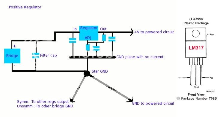
Incidentally I notice on your schematic that you say the groundplane ground carries no current. But you have an input cap to the regulator which will route HF currents through the groundplane. Not really so desirable Suggest adding lowish valued wirewound series resistor prior to this cap (say 0R22 - 0R47).
Incidentally I notice on your schematic that you say the groundplane ground carries no current. But you have an input cap to the regulator which will route HF currents through the groundplane. Not really so desirable
Suggest adding lowish valued wirewound series resistor prior to this cap (say 0R22 - 0R47).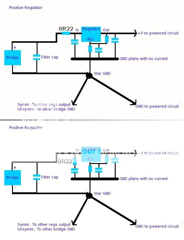
I don't know if this is relevant, but I did not have the required resistor values for a couple of the positions and put two 1/4w metal films in series. Would this give them more power handling? (I think not?)
I would need to open up one of my amps to see which ones these are and to measure the reg modules. If you would like me to do this I will.
Rob.
I would need to open up one of my amps to see which ones these are and to measure the reg modules. If you would like me to do this I will.
Rob.
Thanks Rob but I don't think the resistors are the problem. Much more likely it's the start up as abraxalito has suggested. What traffo are you using (I seem to remember it was a 250VA)? Mine is a 400VA and I am wondering if that is the vital difference between our two circuits. I know that some recommend a soft-start for anything over 300VA.
Do you mean as in the top of bottom diagram?
Yes, the top one is what I meant.
The bottom one is useful if you can't afford the voltage drop of the series R but it still lets HF noise pass through the regulator unchecked. If you were to use this case the R should be a normal carbon or metal film, not wirewound. It doesn't need to dissipate much power.
Using the lightbulb in series with the input slows down the voltage rise considerably - it would most likely prevent the condition where over 40V appears across the reg.
Yes, that's the idea. With a zener between reg 'in' and reg 'out' the output can't easily get more than 33V below the input. The zener voltage could even be much lower, like 12V. Just you'll blow the zener very quickly if you short the output, and the reg may follow very shortly after...
- Status
- This old topic is closed. If you want to reopen this topic, contact a moderator using the "Report Post" button.
- Home
- Amplifiers
- Chip Amps
- Snubberized LM338 regulated PSU problem