I've got two remarks:
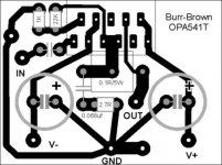
- Shouldn't there be a resistor of 47K/100K from pin 1 to ground to set the input impedance?
-Is the current sense resistor attached to the trace above 'out'? I think it is and that's ok, I just wasn't shure
The rest looks really nice, what program did you use to draw it?
- Shouldn't there be a resistor of 47K/100K from pin 1 to ground to set the input impedance?
-Is the current sense resistor attached to the trace above 'out'? I think it is and that's ok, I just wasn't shure
The rest looks really nice, what program did you use to draw it?
Hi everyone,
Just made the pcbs using pentel pen . I hope it works. 22K to ground from pin 1 will be soldered at the foilside of the pcb. The ground of the supply caps have been joined together before going to the star ground. Thanks.
I'll start soldering as soon as I finish drilling, I hope the pcb works!
JojoD
Just made the pcbs using pentel pen
. I hope it works. 22K to ground from pin 1 will be soldered at the foilside of the pcb. The ground of the supply caps have been joined together before going to the star ground. Thanks.I'll start soldering as soon as I finish drilling, I hope the pcb works!
JojoD
Hi guys!
The pcb works! The 22k was connected at the bottom of the pcb and the grounding was changed to your suggestions.
The 2 amps are powering a 12 inch Targa sub with dual 4 ohms coils (one for each amp) in a vented box. Things around the room are shaking/falling, my wife complains saying the bass is too loud and the windows are rattling .
The sound is very good but if you have other suggestions, please do so.
Thanks,
JojoD
The pcb works! The 22k was connected at the bottom of the pcb and the grounding was changed to your suggestions.
The 2 amps are powering a 12 inch Targa sub with dual 4 ohms coils (one for each amp) in a vented box. Things around the room are shaking/falling, my wife complains saying the bass is too loud and the windows are rattling
.The sound is very good but if you have other suggestions, please do so.
Thanks,
JojoD
- Status
- This old topic is closed. If you want to reopen this topic, contact a moderator using the "Report Post" button.
- Home
- Amplifiers
- Chip Amps
- Pls Check PCB for OPA541...