I've recently got back into playing with my GC's after some time away in Class D land.
I still love the SMPS LM3875 version although at only 12v it clips into my MS Pageant speakers on some tracks at high volume. That said it will drive my old Goodmans 201's well enough.
The Pedja Rogic regulated LM3875 sounds sublime running at +/-26 volts.
I was surprised at how much I liked the LM338 regulated LM3886. So I was thinking of building the snubberised version, and as I have a 30 volt traffo spare, I wondered about using that and then regulating the 42 volt output down to 39.
There are those who reckon the LM chips perform best at higher voltages and I wondered if anybody else had tried this.
Another observation I made in these latest auditions is that I prefer the Black Gate NXQ 47 uF caps on the input to almost any film cap. The exception being a Russion PIO that I only have in 0.1 uF. On the LM338 clone I actually preferred a 47 uF Panasonic ECA lytic to the 2.2 uF polypropylene that was there before. The moral is don't always assume that a film cap is the best option.
Anyway, it's fun to be tinkering around with the clones again.")
I still love the SMPS LM3875 version although at only 12v it clips into my MS Pageant speakers on some tracks at high volume. That said it will drive my old Goodmans 201's well enough.
The Pedja Rogic regulated LM3875 sounds sublime running at +/-26 volts.
I was surprised at how much I liked the LM338 regulated LM3886. So I was thinking of building the snubberised version, and as I have a 30 volt traffo spare, I wondered about using that and then regulating the 42 volt output down to 39.
There are those who reckon the LM chips perform best at higher voltages and I wondered if anybody else had tried this.
Another observation I made in these latest auditions is that I prefer the Black Gate NXQ 47 uF caps on the input to almost any film cap. The exception being a Russion PIO that I only have in 0.1 uF. On the LM338 clone I actually preferred a 47 uF Panasonic ECA lytic to the 2.2 uF polypropylene that was there before. The moral is don't always assume that a film cap is the best option.
Anyway, it's fun to be tinkering around with the clones again.
My customers have been building the updatemydynaco retrofit kits for Dynaco Stereo 120's. It uses a LM3886 run from a regulated power supply at 72 volts.
Here are some links that you might find interesting:
http://www.updatemydynaco.com/documents/AssemblyManualRev2.08.pdf
GT100 Power Amplifier
http://www.updatemydynaco.com/documents/AssemblyManualPowerSupplyReplacementRev2p03.pdf
Here are some links that you might find interesting:
http://www.updatemydynaco.com/documents/AssemblyManualRev2.08.pdf
GT100 Power Amplifier
http://www.updatemydynaco.com/documents/AssemblyManualPowerSupplyReplacementRev2p03.pdf
Last edited:
Welcome back! And thank you for all of the great information you have posted, it is a great resource.
Thanks - nice to be back.
My customers have been building the updatemydynaco retrofit kits for Dynaco Stereo 120's. It uses a LM3886 run from a regulated power supply at 72 volts.
Here are some links that you might find interesting:
http://www.updatemydynaco.com/documents/AssemblyManualRev2.08.pdf
GT100 Power Amplifier
http://www.updatemydynaco.com/documents/AssemblyManualPowerSupplyReplacementRev2p03.pdf
Thanks for the links. That looks like a single rail supply so it would be the equivalent of running at +/-36 volts. But it looks to be an unregulated supply.
You're right...the single 72 volt supply is pretty much the equivalent of +/- 36 Volts. However, the supply is quite well regulated at 72 Volts.
I will readily admit that the schematic is a bit confusing, as the regulator is in the low side of the supply. This does have some advantages, allowing N-Channel pass transistor, plenty of gate drive for low overhead, and a direct connection of the drain (metal tab) to ground, which lowers the thermal resistance.
Update My Dynaco
You're right...the single 72 volt supply is pretty much the equivalent of +/- 36 Volts. However, the supply is quite well regulated at 72 Volts.
I will readily admit that the schematic is a bit confusing, as the regulator is in the low side of the supply. This does have some advantages, allowing N-Channel pass transistor, plenty of gate drive for low overhead, and a direct connection of the drain (metal tab) to ground, which lowers the thermal resistance.
Update My Dynaco
Nice concept djoffe! Given that the biggest outlay on a chip amp is the case and transformer, it's a budget way to a good amp. And green too with the recycled components.
I assume that the large cap on the PCB with the inductor coil around it is the output cap - how does that affect the sound or don't you notice it? It's what has always put me off a single rail GC.
I've never noticed (heard) any problems from the output cap, and it makes a nice coil form for the output inductor.
It's important that the output cap is big enough to not limit the low end. When you measure distortion, there can be a rise at the lowest frequencies and highest powers owing to some non-linearity in the output cap...But with a bit of careful design, it's not an issue.
On the plus side about the output cap, it saves speakers if the output stage fails stuck at the rail. This also saves the cost and potential distortion from an output relay and dc protection circuits.
Update My Dynaco
Hi Nick and yes a warm welcome back. Even though I built MY 3886 and 3875 amps a few years ago I still dip into the Dungeon for tips on various things. There was a time when it was a bit hit and miss as to whether you would get the page you wanted, but it seems fine now.
I built two LM3875 monoblocks using 30-0-30 trannys and the regulated supply on DD. I get about 42v per rail, so nearly on the limit of the chip, but it sounds great to my ears, and has been totally reliable. I recently re-built the amp modules in order to enlarge the heat sinks (they were really small initally - but then I was using 97dB horns), I can now use them with a wider range of speakers.
Rob.
Hi Rob. I had a few problems with free web hosting but I hope that I have found a good host now. And may be I can even add a bit to the Gainclone section.
I presume that you used the LM338 regulator for your clones? If so that is what I will be copying for an LM3886 amp. I am hoping to have six or seven different GC's all built to completion so that I can compare them all quickly. In the past it has been a case of of stripping down one version to get parts to build another. Not the ideal way to make accurate comparisons!
I presume that you used the LM338 regulator for your clones? If so that is what I will be copying for an LM3886 amp. I am hoping to have six or seven different GC's all built to completion so that I can compare them all quickly. In the past it has been a case of of stripping down one version to get parts to build another. Not the ideal way to make accurate comparisons!
Rob - I'm just re-reading the regulated/+snubberized thread again and Carlos stated
"On this PSU you should have around 10V more voltage before the regs, so there's plenty of voltage to sag."
So it may be best to stick to around 32 volts output with a 30 volt traffo (42 volts before regulation). That said, I guess you haven't found a problem running yours higher. But are you sure you are getting 42v after regulation? That would mean no drop out at all across the regs!
I've never noticed (heard) any problems from the output cap, and it makes a nice coil form for the output inductor.
It's important that the output cap is big enough to not limit the low end. When you measure distortion, there can be a rise at the lowest frequencies and highest powers owing to some non-linearity in the output cap...But with a bit of careful design, it's not an issue.
On the plus side about the output cap, it saves speakers if the output stage fails stuck at the rail. This also saves the cost and potential distortion from an output relay and dc protection circuits.
Update My Dynaco
I haven't ever tried having a coil around a capacitor. So the following is mostly just pure speculation.
An output coil should supposedly be an "air core" type, to avoid hysteresis distortion and potential saturation (although saturation shouldn't be a problem in this case, duh).
With the cap inside it, it would no longer be an air core coil. I'm not sure if aluminum would have much of an effect, or not. But it might. And there's other conductive stuff, in caps, too.
So, have you measured the actual inductance of the coil, with the cap inside the coil? Calculated air core values would be changed by the presence of the metal etc in the capacitor.
Also, in addition to worrying about the possibility of hysteresis-type distortion from the coil, the coil's electromagnetic field might have some undesirable effect on the cap's performance, too.
That is all just speculation, of course. But have you tried an actual air core coil (with the same measured inductance, which would probably mean it would be a different size, which, unfortunately, would mean it would also have a different DCR, which might affect the comparison), to compare the sound?
Last edited:
I presume that you used the LM338 regulator for your clones?
Yes.
Rob - I'm just re-reading the regulated/+snubberized thread again and Carlos stated
"On this PSU you should have around 10V more voltage before the regs, so there's plenty of voltage to sag."
So it may be best to stick to around 32 volts output with a 30 volt traffo (42 volts before regulation). That said, I guess you haven't found a problem running yours higher. But are you sure you are getting 42v after regulation? That would mean no drop out at all across the regs!
Nick. I measured them recently after the re-build and that is what the meter said. I will check it again.
Gootee,
You ask good questions about the inductor around the cap. In the particular geometry I use, winding the inductor on the cap definitely reduces the amount of inductance that you get.
When I had designed the amps, I noticed this, and thus made the measurement both ways on an LCR bridge at 100 kHz. As you asked the question, I revisited the measurements in a better way than just on the LCR bridge.
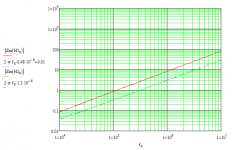
I used a network analyzer to get a look at the impedance versus frequency, then matched it to equivalent networks for impedance. With about 5 turns on a 35 mm diameter capacitor, the inductance was 0.5 uH. Off the capacitor, the inductor is 1.3 uH. Thus, the difference is significant.
As to distortion, the figures that I get for THD+N bottom out around 0.002% into an 8 Ohm load, and that still includes a bit of noise. So I think the arrangement of the inductor around the cap is pretty blameless for distortion.
You ask good questions about the inductor around the cap. In the particular geometry I use, winding the inductor on the cap definitely reduces the amount of inductance that you get.
When I had designed the amps, I noticed this, and thus made the measurement both ways on an LCR bridge at 100 kHz. As you asked the question, I revisited the measurements in a better way than just on the LCR bridge.
I used a network analyzer to get a look at the impedance versus frequency, then matched it to equivalent networks for impedance. With about 5 turns on a 35 mm diameter capacitor, the inductance was 0.5 uH. Off the capacitor, the inductor is 1.3 uH. Thus, the difference is significant.
As to distortion, the figures that I get for THD+N bottom out around 0.002% into an 8 Ohm load, and that still includes a bit of noise. So I think the arrangement of the inductor around the cap is pretty blameless for distortion.
Attachments
Gootee,
You ask good questions about the inductor around the cap. In the particular geometry I use, winding the inductor on the cap definitely reduces the amount of inductance that you get.
When I had designed the amps, I noticed this, and thus made the measurement both ways on an LCR bridge at 100 kHz. As you asked the question, I revisited the measurements in a better way than just on the LCR bridge.
I used a network analyzer to get a look at the impedance versus frequency, then matched it to equivalent networks for impedance. With about 5 turns on a 35 mm diameter capacitor, the inductance was 0.5 uH. Off the capacitor, the inductor is 1.3 uH. Thus, the difference is significant.
As to distortion, the figures that I get for THD+N bottom out around 0.002% into an 8 Ohm load, and that still includes a bit of noise. So I think the arrangement of the inductor around the cap is pretty blameless for distortion.
djoffe,
Thanks for the detailed response, and the extra effort!
I just tried something similar, after finally finding my Tonghui TH2821A LCR meter, at 10 kHz and 1 kHz. I used an old 15mm x 50 mm axial electrolytic cap and wrapped about 5 turns of 14-gauge stranded lamp cord onto it. At 10 kHz, the inductance measured about 0.3 uH when on the cap and about 0.5 uH off the cap. At 1 kHz, the then-1-digit-only display didn't change, with the coil on or off the cap, staying at 0.5 uH. At 100Hz, it wouldn't measure it, reporting zero.
Cheers,
Tom
A couple of low voltage drop ways to get virtual dual mono from 1 transformer and sound very similar to regulated:
1
The low voltage drop K-Multi capacitive multiplier (individual units for left and for right). Thanks to diyaudio.com member Keantoken for this one.
2
Transformer > Bridge rectifier > Cap bank > Cables left and right > Series Diode > Cap (330uF to 3300uF) > Amplifier
In this example the series diodes on the rails (both v+ and v- have series diode) are individualized per left and right amplifiers (there's 4 series diodes, v+ left, - left, v+ right, v- right) providing a bit of isolation. Thanks to diyaudio.com member TheProf for this one.
P.S.
I wanted to mention that there's ways to get similar sound to regulated, without actually using regulators.
Last edited:
- Status
- This old topic is closed. If you want to reopen this topic, contact a moderator using the "Report Post" button.
- Home
- Amplifiers
- Chip Amps
- Higher voltage regulated GC