Hello...
Im currently building a lm1875
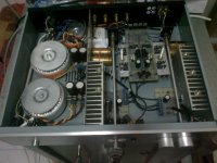
Im building a dual mono... And im using toroidal transformer 160vac, with secondary output 2x18v
First of all, i was wiring the PSU...and i've got the output is 25V and i think it is great....
The im wiring up my amp.... Without input an output wired on my amp board, i was checkin the dc offset....
And i've got 22V !!!
The im browse any internet, and ive got 2 ways to measuring the dc offset
1. Short the input
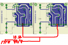
2. Put 10 ohm resistor across the output
I did the first way, and got the same result 22v, but not do the second way yet...
Did i just broke my ic ????
Im currently building a lm1875
Im building a dual mono... And im using toroidal transformer 160vac, with secondary output 2x18v
First of all, i was wiring the PSU...and i've got the output is 25V and i think it is great....
The im wiring up my amp.... Without input an output wired on my amp board, i was checkin the dc offset....
And i've got 22V !!!
The im browse any internet, and ive got 2 ways to measuring the dc offset
1. Short the input
2. Put 10 ohm resistor across the output
I did the first way, and got the same result 22v, but not do the second way yet...
Did i just broke my ic ????
Did i just broke my ic ????
Not necessarily, you could be missing input ground connection.
Also, adding a load will not affect offset reading.
thank you for replying....
is it same thing between loading 10ohm resistor across the output and put a speaker on the output ???
coz i think i just blew up my speaker ( lucky for me, its an unused speaker )
but when i load a speaker... i still got 22v on my output ( measure from + and - at the speaker )
but when i saw peter daniel thread, he has a huge dc too http://www.diyaudio.com/forums/audi...-kit-building-instructions-9.html#post1521393
but my question is.... i dont know what the function of 10ohm resistor... sorry i'm noob here......
and please find the schematic at the attachment.... i will attach my amp tonight
thank you very much
Last edited:
Sorry about your speaker.
Voltages only exist between two points. For the output voltage, your wall ground is not one of those points.
Output voltage must be measured only between the two output connection points (where a speaker would be connected).
NO load should be used (no resistor and no speaker), when measuring output offset voltage.
The signal input should be shorted (connected) to the signal input ground, when measuring output offset voltage. (But I would also measure it when the source device is connected and turned on, but with no signal.)
You should NEVER connect speakers until AFTER you have checked the output offset, and verified that it is low-enough.
Output offset should typically be a few 10s of millivolts, or less.
Last edited:
The power supply should give +25V and -25V, total 50V from plus to minus.First of all, i was wiring the PSU...and i've got the output is 25V and i think it is great....
@gootee : no not yet.... i was wiring v+ g- g+ v- from power supply to amp board.... haven't do the other wiring... is this the problem ??
@godfrey : yes i mean ±25V
i decided to buy a new ic today... and decided to switch the old one tonight.... hope everything going well
@godfrey : yes i mean ±25V
i decided to buy a new ic today... and decided to switch the old one tonight.... hope everything going well
The problem is the ic...
After i change the ic, ive got 1mv on both channel
But something weird happened....
After im wiring a preamp into the lm1875, ive got output 17v ( again ) and 10mv on the other one.... I dont know what happened..... :'(
When i put off the preamp, i still got the same dc offset... 17V
*havent wiring any grounding yet, and dont put anything on input and output*
After i change the ic, ive got 1mv on both channel
But something weird happened....
After im wiring a preamp into the lm1875, ive got output 17v ( again
) and 10mv on the other one.... I dont know what happened..... :'(When i put off the preamp, i still got the same dc offset... 17V
*havent wiring any grounding yet, and dont put anything on input and output*
@gootee : no not yet.... i was wiring v+ g- g+ v- from power supply to amp board.... haven't do the other wiring... is this the problem ??
<snipped>
What is the ground of your amplifier output connected to?
How do you have G- and G+ wired to the amplifier circuit??
There can be only ONE ground.
Guys, please help me to do the grounding
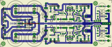
as attach is dual mono lm1875 integrated with stereo CMoy as a preamp
i have 4 different output through 1 rotary switch and 2 different output through 1 rotary switch
nb. please ignore the 10ohm resistor at the pic
as attach is dual mono lm1875 integrated with stereo CMoy as a preamp
i have 4 different output through 1 rotary switch and 2 different output through 1 rotary switch
nb. please ignore the 10ohm resistor at the pic
Attachments
Guys, please help me to do the grounding
as attach is dual mono lm1875 integrated with stereo CMoy as a preamp
i have 4 different output through 1 rotary switch and 2 different output through 1 rotary switch
nb. please ignore the 10ohm resistor at the pic
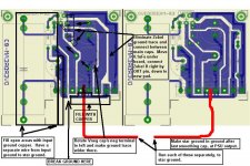
See the attached jpg image.
I couldn't fit everything on the image that I wanted to include. But the important ones are:
1. Flood-Fill input area with copper, CLOSE to all traces and pads (to eliminate enclosed loop area between signal and signal ground.
1a. DISCONNECT input ground from all other grounds.
1b. Run a SEPARATE WIRE from the input ground area to the star ground.
2. Change Zobel to connect very close to output pin and directly to ground between caps.
3. Move 0.1 uF caps to bottom of board, connecting right at power pins.
4. Move large caps closer to power pins.
5 Widen the ground, power rail, and output traces.
6. Make the star ground point be at the output of the power supply, in the smoothing caps' ground but AFTER the last smoothing cap.
7. Run a separate wire to the star ground, for each amp's main ground.
I'm not sure if the speaker ground should go directly to the star ground, separately, or should come back to the amp board first.
Cheers,
Tom
Attachments
Last edited:
Hi Tom
thank you for your advice
yesterday i was wiring the grounding
i tied together input ground and output ground ( from binding post and rca )
then i mount to chassis
what i've got ???
no sound at my cpeaker.. just clap... clap... clap... clap...clap....
@tom : maybe you can give me an advice without changging the pcb ???
thank you very much
Overdream,
It looks like the power supply has named outputs that match the amplifier boards' named connections.
You will need to make the wires mentioned below, if you don't already have them installed. If you DO already have some or all of the wires installed, make sure that they are correct.
Make two sets of two pairs of wires each, for two sets of a) V+, G+ pair and b) V-, G- pair, that will go from the power supply to the two amp boards. Twist each pair before cutting off and stripping the ends of the wires, with about four twists per inch, so you will get the lengths right, i.e. including the twisting.
Connect the V-, G+, G-, and V+ from the power supply to each of the amp boards, using the wire pairs you just made. Those should fill positions 3, 4, 5, and 6, of both amplifiers' terminal blocks.
Twist/measure/cut two more pairs, for the left and right IN and GND, that will go from the signal input jacks to the preamp board IN and GND connections. NOTE that the signal input jacks' grounds should NOT be connected to the chassis, near the jacks. Check them with your multimeter, before the other ends of the wires are connected (Ohms not small; should be "off-scale high").
Twist/measure/cut two more pairs, for the left and right IN and GND, that will go from the preamp OUT and GND connections to the amp boards' IN and GND, which will be positions 1 and 2 on the amps' terminal blocks.
Install a bolt in the chassis, which will be the star ground. The threaded part of the bolt will be inside the chassis, and needs to be positioned where you can access it.
You will need round lugs that fit onto the bolt, that also can have a wire crimped and/or soldered to them.
Make two wires, to go from each amp's terminal block's Position 7 to the star ground bolt.
Make two wires, to go from each speaker jack's GND or "-" to the star ground bolt.
Make two wires, to go from the amp boards' terminal blocks' Position 8 to the speaker jacks' "+" or OUT connections.
I'm not sure if a ground connection from the power supply to the star ground is still needed or not. (You can try it as decribed, so far, and maybe we will find out.)
I think that you will either need a wire from the power supply output ground to the star ground, OR, connect the speaker jacks' GND wires directly to the power supply's G+ nd G- connections on the power supply PCB.
You should use a bulb tester between the AC Mains and your power supply, until everything has been checked out.
Before connecting any speakers, you should short each IN to GND at each signal input jack and measure the DC voltage across each speaker OUT/GND connector and make sure that the DC voltage across both speaker connectors is near zero, for every volume setting.
Once all of those wires are connected and the DC offsets have been tested, it might give you some sound. If not, maybe I forgot something (or maybe something else is wrong). If there is sound, there might also be some hum. If there's hum, we can go from there, and try to eliminate it, after we can get some output sound.
Cheers,
Tom
Last edited:
Hi guys
Problem solved !!!
Thank you all
This is the solution...
I put the input ( rca ) ground and the potentio ground to preamp board ground....
I put the output ground to the amp board
Then i put all ground channel ( pre amp, and amp board ) together as a star ground then connect it to chassis through 10ohm resistor...
I've got no humming, small dc offset, a lil bit hissing on my headphone out, but its ok...
Thank you all
Hi guys
Problem solved !!!
Thank you all
This is the solution...
I put the input ( rca ) ground and the potentio ground to preamp board ground....
I put the output ground to the amp board
Then i put all ground channel ( pre amp, and amp board ) together as a star ground then connect it to chassis through 10ohm resistor...
I've got no humming, small dc offset, a lil bit hissing on my headphone out, but its ok...
Thank you all
somebody should alert him...
- Status
- This old topic is closed. If you want to reopen this topic, contact a moderator using the "Report Post" button.
- Home
- Amplifiers
- Chip Amps
- HUge dc offset