I have a small 150w power invertor that I can gut to make a +/- supply and fit all 3 amps inside. It's fairly simple with a regulated PWM push-pull step-up convertor then a H-bridge after that with another PWM IC driving it to make "AC". The two stages may be easy to seperate. Looks like only a shutdown signal from the second PWM going back to the first. Could be promising to make a bipolar supply with.
It would be best to sepparate the two PWM and take the output voltage from the first one's circuit, but even that way you would still need much power from the battery wich i don't think it can cope by it's self with the demands so only with the engine started you could use the device.
I think the battery is rated 9-10ah and a 1000cc twin is NOT easy to push start. lol
Right about the inverter. I'd ditch the second PWM and AC stage. I'd place the amps in that area. I'm not sure if the secondary has a center tap or not. If not, I could probably use a transformer from a PC power supply. I've seen a few of those with a CT primary (120v) and CT secondary (12v). If I could find a car amplifier small enough I'd use it but all the little ones I could find use ICs running off the 12v supply. If that's the case then I'd rather make my own.
Right about the inverter. I'd ditch the second PWM and AC stage. I'd place the amps in that area. I'm not sure if the secondary has a center tap or not. If not, I could probably use a transformer from a PC power supply. I've seen a few of those with a CT primary (120v) and CT secondary (12v). If I could find a car amplifier small enough I'd use it but all the little ones I could find use ICs running off the 12v supply. If that's the case then I'd rather make my own.
There is a big difference between jumpstarting an engine and powering an amplifier, the engine requires much more power than the amplifier granted, but that is only for a few seconds, after that the alternator takes the bulk of the charge/load, on the othe hand the amplifier requires less power but continuosly as long as you listen to music on it, so the battery even if it is rated at let say 10A/h it can give more than that ( much more ) for a short time without discharging much, but it cannot sustain an important load continuosly too much time, and an 150W converter would require at least 13A constant from the battery, now you understand why the battery would discharge quikly.
It is not such a big problem if the converters transformer does not have a center tap on it's output, you can simply reconstruct the secondary coil to your specs, just make sure you respect the turn ratio and other specs on that converter ( if any ).
It is not such a big problem if the converters transformer does not have a center tap on it's output, you can simply reconstruct the secondary coil to your specs, just make sure you respect the turn ratio and other specs on that converter ( if any ).
The tda7560 looks like a nice chip. http://www.st.com/internet/com/TECHNICAL_RESOURCES/TECHNICAL_LITERATURE/DATASHEET/CD00001962.pdf
Can I parallel the outputs of any of these ICs even if they're internally BTL?
Can I parallel the outputs of any of these ICs even if they're internally BTL?
There is a big difference between jumpstarting an engine and powering an amplifier, the engine requires much more power than the amplifier granted, but that is only for a few seconds, after that the alternator takes the bulk of the charge/load, on the othe hand the amplifier requires less power but continuosly as long as you listen to music on it, so the battery even if it is rated at let say 10A/h it can give more than that ( much more ) for a short time without discharging much, but it cannot sustain an important load continuosly too much time, and an 150W converter would require at least 13A constant from the battery, now you understand why the battery would discharge quikly.
It is not such a big problem if the converters transformer does not have a center tap on it's output, you can simply reconstruct the secondary coil to your specs, just make sure you respect the turn ratio and other specs on that converter ( if any ).
I understand batteries. I've built many electric vehicles.
The inverter draws 250ma without a load. It's input is proportionate to it's output so if I'm drawing 120w (120v@1a) it's drawing 120w (12v@10a) minus the efficiency of the inverter of course. I don't expect the amplifiers to be operating at peak output 100% of the time either. The battery in the bike is SLA and they seem to handle constant draws. I use one on my test bench often. No doubt it can push current if it needs to. Ask my how many jumpers I have melted. lol One of these days I'll put a fuse on it.
I think you have e deciding issue, too much options do more harm than good sometimes.
What you need toi understand is that you cannot espect a high power audio sistem on a motorcycle no matter what the solution choosen is, on the other hand 20W for a good woofer is often more than enough, the same for the other 2 speakers so you have to make up your mind on what you can do with, an simple IC amplifier at 12V ( BTL or otherwise ) and that way you can run the amplifier even with the engine off but not too much time, or you use an converter to get more power but it is more complicated and you can only run the amp at high volume with the engine started, the choice is yours")
What you need toi understand is that you cannot espect a high power audio sistem on a motorcycle no matter what the solution choosen is, on the other hand 20W for a good woofer is often more than enough, the same for the other 2 speakers so you have to make up your mind on what you can do with, an simple IC amplifier at 12V ( BTL or otherwise ) and that way you can run the amplifier even with the engine off but not too much time, or you use an converter to get more power but it is more complicated and you can only run the amp at high volume with the engine started, the choice is yours
I'm still left searching for a 4ch single ended IC to make a 2.1 system by bridging ch3 and 4. -or- Use two ICs. A 2ch BTL? for the fronts and a single channel for the sub. In the ICs I've been fiddling with so far it seems that 12v is plenty to provide the power I need into 4ohm speakers.
Is any way better then the other? My thought was a 4ch would use less components but I can't find a "high power" 4ch IC other then the TDA1554Q http://skory.gylcomp.hu/alkatresz/tda1554q_cnv_2.pdf I'm sure there are higher then 11w versions of it. I've been digging on mouser but their selection guide is a mess.
Is any way better then the other? My thought was a 4ch would use less components but I can't find a "high power" 4ch IC other then the TDA1554Q http://skory.gylcomp.hu/alkatresz/tda1554q_cnv_2.pdf I'm sure there are higher then 11w versions of it. I've been digging on mouser but their selection guide is a mess.
You still don't get it:
-In Class AB ( or B ) on 12V power supply no matter what IC you use, you cannot get on single ended amplifier more than 10W on 4 Ohm load ( that 11 figure is forced with verry high THD ), it is not fisicaly possible.
-On a BTL config at same 12V power supply, same class same load you can only get about 20W maximum no matter what IC is used.
-The only way to troubleshoot this limitation is class H like TDA1562, but i think that is forcing the issue.
So bottom line is, you have a given voltage rail wich the output devices cannot exeed so no matter what the IC pdf says, it is not possible to get more.
I thought you can get up to ~20w or so into 4ohm. 12v into 4ohm is 3a *12 = 36w -IF- it could swing rail to rail which it can't but only 10w? I know they can do better then that. Maybe 10w into 8ohm. Or is this where the whole SE vs. BTL comes into play? I have been thinking SE could swing rail to rail but that's probably my mistake.
No one here has said until now that 10w is the limit with a 12v supply. OK... So... It there a 3ch BTL (20w x3) IC?
No one here has said until now that 10w is the limit with a 12v supply. OK... So... It there a 3ch BTL (20w x3) IC?
Last edited:
I see you still have much to learn. it's like this:
The amplifier has to drive the signal on both phases, possitive and negative ( think of it as one center line wich is the refference and the signal goes above and beyound that line ), now on a simetricall supply it is easy, the amplifier has both positive and negative voltage to help it drive the signal, but when using a single supply the amplifier first has to split the voltage so that it can have a refference point at the middle from wich it can drive the signal, on both supply config the amplifier has supply rails that it cannot exeed, so on a 12V single supply the amplifier split's it in half, and the SE config has at the output before the dc decoupling capacitor about half the Vin ( 6V for this ), those are the rails for the signal, 6V; now the BJT output devices in the IC need for them selves about .6-.7V to turn on so you are left with 5,4V maximum signal rail possible, and knowing that Pout=V^2/R you do the math.
The amplifier has to drive the signal on both phases, possitive and negative ( think of it as one center line wich is the refference and the signal goes above and beyound that line ), now on a simetricall supply it is easy, the amplifier has both positive and negative voltage to help it drive the signal, but when using a single supply the amplifier first has to split the voltage so that it can have a refference point at the middle from wich it can drive the signal, on both supply config the amplifier has supply rails that it cannot exeed, so on a 12V single supply the amplifier split's it in half, and the SE config has at the output before the dc decoupling capacitor about half the Vin ( 6V for this ), those are the rails for the signal, 6V; now the BJT output devices in the IC need for them selves about .6-.7V to turn on so you are left with 5,4V maximum signal rail possible, and knowing that Pout=V^2/R you do the math.
I see you still have much to learn. it's like this:
The amplifier has to drive the signal on both phases, possitive and negative ( think of it as one center line wich is the refference and the signal goes above and beyound that line ), now on a simetricall supply it is easy, the amplifier has both positive and negative voltage to help it drive the signal, but when using a single supply the amplifier first has to split the voltage so that it can have a refference point at the middle from wich it can drive the signal, on both supply config the amplifier has supply rails that it cannot exeed, so on a 12V single supply the amplifier split's it in half, and the SE config has at the output before the dc decoupling capacitor about half the Vin ( 6V for this ), those are the rails for the signal, 6V; now the BJT output devices in the IC need for them selves about .6-.7V to turn on so you are left with 5,4V maximum signal rail possible, and knowing that Pout=V^2/R you do the math.
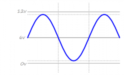
For lack of a better term I'll call it 6v of "bias". If it swings up to 11 and down to 1 (to choose even numbers) then it has 10v p-p of swing. Correct? Everything your telling me I understand. What I don't understand is how 10v can't produce more then 10w. Where are you coming up with it only being able to swing from 1/2vcc and down? Why not up?
You still don't get it..( damn..am i so lousy at explayning stuff?...)
The term is rail voltage, and it cannot swing upt to 10V and down 1V, it has to swing equally up and down, so it has to split the voltage in half, this example is at 6V, but it will not have a total of 12V peak to peak at the output, it cannot, because the refference point is already set in the middle of that so at the output without the dc cap it can only have +6v or -6V. Now you understand?
The term is rail voltage, and it cannot swing upt to 10V and down 1V, it has to swing equally up and down, so it has to split the voltage in half, this example is at 6V, but it will not have a total of 12V peak to peak at the output, it cannot, because the refference point is already set in the middle of that so at the output without the dc cap it can only have +6v or -6V. Now you understand?
Yes that's how I understood it in the first place. You said "you are left with 5,4V maximum signal rail possible" Did you mean +/-5.4v? Which is 10.8v rail to rail swing. I used 11 and 1 as my example to keep numbers even. With a 6v center, swinging from 1v to 11v is +/-5v.
I drew this to show my understanding of the output.

I drew this to show my understanding of the output.
Attachments
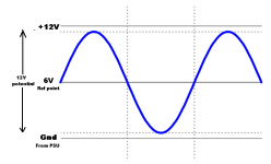
It's like this:
The signall allways starts from the refference point wich in this case is the middle 6V, and it only goes or above or beyound that point, but IT CANNOT GO BOTH WAYS AT THE SAME TIME, it can only go UP or DOWN at any time so the signall CANNOT BE more than 6V possitive or negative ( that is above or beyound that refference point ) minus about .6 needed by the bjt's.
If this doesn't helps you either than i suggest a boock for you to read urgently, it is called: The Art Of Electronics, read it cover to cover and you will surely undertand, cus if this does not help you than i give up, and call you a lost cause.
Attachments
Last edited:
JESUS!!!!! Excuse the question but...how old are you?...i cannot believe tha someone can be so....well for lack of a better word..close minded...don't you have any imagination?
How many times must i tell you that the actual level of the signal swing can only be about 5,4V? how many times must a tell you that the signal has a possitive and a negative phase and they alternate according to the signal, so even thow the peak to peak level it is about 10V ( or so ), the actual level of the signal swing cannot be more than 5,4V because the swing starts ALWAYS from the middle point and goes either UP or DOWN, it cannot go both ways at the same time, it can only go either possitive or negative from the middle point.
If you still don't get it than stop wasting our time and go to school!!!
Just give up Marian; don't get frustrated over this guy.
If he doesn't want to understand why single ended output power from 12V is only about ~4.5W (low distortion "RMS", not even accounting for losses) then he can learn on his own.
Just leave him with this.....
Audio power - Wikipedia, the free encyclopedia
If he doesn't want to understand why single ended output power from 12V is only about ~4.5W (low distortion "RMS", not even accounting for losses) then he can learn on his own.
Just leave him with this.....
Audio power - Wikipedia, the free encyclopedia
I do want to understand. That's why I'm asking. If I knew EVERYTHING about electronics, I wouldn't be here. What's a forum for if we can't ask questions? I understand quite a bit about quite alot. Ever think your not explaining it right or leaving out key facts that explain how the output stages work? Grass is green, fine, I got it. Now explain WHY. Just saying 10w is 10w is 10w you only get 10w that's all you get is 10w. Trust me I'm on the same page. How I explain my interpretation may be as different from your understanding as your explination is different from my understanding.
To get back to the ORIGINAL topic. What is THE highest power IC available using the least number of components that can do 2.1 in a single IC...... -or- ......2 ICs using a 2ch BTL + 1ch BTL to make a 2.1 system. Is the TDA1562 my best bet? Are there others you recomend so I can choose? Or do we want to keep arguing over power output?
To get back to the ORIGINAL topic. What is THE highest power IC available using the least number of components that can do 2.1 in a single IC...... -or- ......2 ICs using a 2ch BTL + 1ch BTL to make a 2.1 system. Is the TDA1562 my best bet? Are there others you recomend so I can choose? Or do we want to keep arguing over power output?
Last edited:
- Status
- This old topic is closed. If you want to reopen this topic, contact a moderator using the "Report Post" button.
- Home
- Amplifiers
- Chip Amps
- Looking for the right IC for an amp project.