A few months back, I built a successful LM3886-based amp. I copied the design almost verbatim to new (fab'd) PCBs, and assembled eight of them. Now I'm finding negative DC on the output. I tested two with identical results.
Ugh... I know I must be missing something simple, so would you mind taking a look?
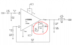
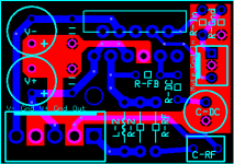
Attached is the reference schematic -- based on ESP Project 19 -- and the PCB design.
On the schematic, the mute circuitry (circled in red) has been moved off-board. There will be five of these modules in each speaker cabinet (4 woofers, 1 tweeter bank) so the PSU, input buffer, crossover, and mute controller will be on a separate PCB.
I'm using a high-power wall-wart with individual +DC, -DC, Ground, and +5v (not used) for testing. This is plugged into a Variac for now. I tested with about +7/-7 on the PSU rails. Probing the pins of the chip showed this (DC volts), re: ground:
V-: -7v
V+: +6.6v
Out: -4.5v
In-: -4.5v
In+: 0v
Mute: -2.2v
No input (but there is a resistor to ground on the PCB). No load. The two test subjects are mounted to a temporary heatsink. No thermal paste, but I did use one of those uber-thin thermal pads. It's bolted to the sink, with no attempt to isolate the V- supply.
Any clues? Again, the older PCB on which this is based works perfectly.
Ugh... I know I must be missing something simple, so would you mind taking a look?
Attached is the reference schematic -- based on ESP Project 19 -- and the PCB design.
On the schematic, the mute circuitry (circled in red) has been moved off-board. There will be five of these modules in each speaker cabinet (4 woofers, 1 tweeter bank) so the PSU, input buffer, crossover, and mute controller will be on a separate PCB.
I'm using a high-power wall-wart with individual +DC, -DC, Ground, and +5v (not used) for testing. This is plugged into a Variac for now. I tested with about +7/-7 on the PSU rails. Probing the pins of the chip showed this (DC volts), re: ground:
V-: -7v
V+: +6.6v
Out: -4.5v
In-: -4.5v
In+: 0v
Mute: -2.2v
No input (but there is a resistor to ground on the PCB). No load. The two test subjects are mounted to a temporary heatsink. No thermal paste, but I did use one of those uber-thin thermal pads. It's bolted to the sink, with no attempt to isolate the V- supply.
Any clues? Again, the older PCB on which this is based works perfectly.
Attachments
Yes, I know, designed for 20v minimum, and under 12v (which I've exceeded) the undervoltage protection should kick in and mute the output. Nowhere in the datasheet does it say that nearly full-rail negative DC is the protection applied, and I began testing at the supply's minimum output at ~+/-3v and worked up from there.
I will try full +/-15v tomorrow, but I suspect this particular sign of trouble is not the result of underpowering. If I'm wrong, I worry about the safety of a DC-coupled load. :-/ Power supply issues could cause some real trouble if this is expected behavior.
For everyone's sanity, the final PSU is a 250va toroid, 36vct. The wall wart is JUST for initial smoke testing.
throw away the wall wort.
Build a mains bulb tester (BT). Use your BT to check the wiring of your mains transformer. Then check the wiring of the PSU via the BT. Now add on the amplifier and again check via the BT.
When you have completed ALL changes and additions and modifications, only then do you power up direct off the mains.
If the bulb lights up you know you have to "find the fault" before you can proceed.
Check if you R-G 22k is properly grounded. If your R-G isnt grounded you will have DC - 2-3v on the output...
Will do.
throw away the wall wort.
Build a mains bulb tester (BT). Use your BT to check the wiring of your mains transformer. Then check the wiring of the PSU via the BT. Now add on the amplifier and again check via the BT.
Isn't that more or less the same as testing through a Variac? The bulb tester is effectively a current limiter, right? That's kind of what I'm achieving through limiting the voltage supply, I thought. If I'm missing something, please clarify. I appreciate the advice, just trying to understand why the bulb approach is inherently better/safer.
FWIW, the full-fledged power supply is known-good -- complete with fuse(!), transformer, rectifier, and 5x2200uF per rail. I only favor the wall wart PSU at this stage because it has handy banana plug leads that mate well with alligator clips for quick connections while building and testing. I have the full Molex plug setup on the PCB, so the trafo PSU is perfectly doable, just not as convenient. Also kludgy without a case.
You guys think this is potentially a PSU issue? Admittedly, I never got to low-voltage test the older (working) design because it has a transistor-controlled relay to connect the rails. At low voltages, the transistor wasn't saturated and wouldn't close the relay, so there was no possibility of powering up at less than about +/-12vdc. Maybe I'm just seeing this behavior because it's only just now possible to underpower it. Still, I don't like the implications of DC on the output while ramping up to (or down from) full power.
Thanks for the replies -- I'll test further and get back to you.
You guys were absolutely right. Once I brought the voltage up higher, the offset went to 0.00v. I thought for sure the under-voltage protection would prevent DC offset on the output at less than minimum supply. Does that ever cause any problems, or is there no current drive under those conditions? Anyone know? I'd hate to lose a driver if the supply ever drops unexpectedly.
")
- Status
- This old topic is closed. If you want to reopen this topic, contact a moderator using the "Report Post" button.
- Home
- Amplifiers
- Chip Amps
- What I do? Simple LM3886, DC on output