So I just purchased a bunch of BUF634T and was thinking about making a power amp out of them since they can be so easily paralleled. How does 40 per channel sound in a BTL configuration? With regluated +/-18V supplies that should be good for a clean 40Wrms per channel and almost 3W of Class-A goodness.
Does this sound like a stupid waste of nearly $600 in parts (payed way less than that btw)? I could easily sell them for a profit, but wasting good parts on dumb ideas is an addiction of mine.
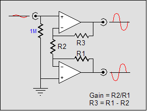
I like simple, so I would just wrap them in the feedback loop of something like this....
Does this sound like a stupid waste of nearly $600 in parts (payed way less than that btw)? I could easily sell them for a profit, but wasting good parts on dumb ideas is an addiction of mine.
I like simple, so I would just wrap them in the feedback loop of something like this....
sell them and burn bunch of mosfets or jfets in some project
Too dumb for discrete circuits; I prefer to stay out of the solid state forum where the big boys play. The "stupidness" of this idea is the only real motivator here.
BUF634T is a unity gain buffer. Where's the voltage gain coming from? The schematic you show is not relevant!. There's no inverting input accessible to you.
Sorry, the picture is of the balanced output circuit I would use to drive the buffers for a BTL configuration. The buffers would be inserted between the op-amp outputs and feedback resistors.
R1=20K
R2=1k
R3=19K
I can already see your build. A printed circuit board [say 2 feet long by 6 inches wide per channel] with 2 rows of repeating low power amplifying units. Clearly, the BUFs will be on heatsinks along both of the long sides of the PCB. Their power outputs will then merge to the center of the PCB via small ohm high watt resistors [for isolation]. This build is feasible. Best regards.
No dumb idea. See
http://www.diyaudio.com/forums/chip-amps/174540-doug-selfs-ne5532-power-amp-thoughts-anyone.html
http://www.diyaudio.com/forums/chip-amps/174540-doug-selfs-ne5532-power-amp-thoughts-anyone.html
Last edited:
I can already see your build. A printed circuit board [say 2 feet long by 6 inches wide per channel] with 2 rows of repeating low power amplifying units. Clearly, the BUFs will be on heatsinks along both of the long sides of the PCB. Their power outputs will then merge to the center of the PCB via small ohm high watt resistors [for isolation]. This build is feasible. Best regards.
Whoa now, that's way too much work.

No PCB's for this one. I will clamp them all together in a horizontal row with little pieces of aluminum plate between each one for heatsinks. The two rows will form the sides of the amp. All the pins will be folded over each other and soldered together. Local supply decoupling soldered directly on each IC.
The BUF634 can be paralleled pin for pin and doesn't need any external resistors to isolate the outputs. I believe they already have 10 Ohm output resistors internal to the IC; at least I remember reading that before.
Yeah that's pro; this is the technically challenged version.


Attachments
the sweet spot is around 10, higher than this and your barrier to more useable power becomes the voltage swing in the VAS and buffer itself. you could parallel 8-10 for each amp, then bridge 2 of those amps for each channel
I guess you saw this project from opc? using the PCB for heatsink and higher performance obviously, but same idea. silly idea? haha this amp produced the best numbers within its power band (up to 15wpc) that ive ever seen.
LPUHP
I guess you saw this project from opc? using the PCB for heatsink and higher performance obviously, but same idea. silly idea? haha this amp produced the best numbers within its power band (up to 15wpc) that ive ever seen.
LPUHP
Attachments
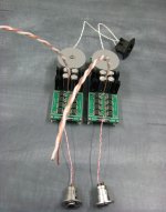
Here you can see BUF amplifier:
Prophetmaster's Class "A" Power Amplifier ñ âûõîäíûì êàñêàäîì íà 41 øò. BUF634T
Russian text, but pictures can be seen.
Prophetmaster's Class "A" Power Amplifier ñ âûõîäíûì êàñêàäîì íà 41 øò. BUF634T
Russian text, but pictures can be seen.
Last edited:
Whoa now, that's way too much work.
No PCB's for this one. I will clamp them all together in a horizontal row with little pieces of aluminum plate between each one for heatsinks. The two rows will form the sides of the amp. All the pins will be folded over each other and soldered together. Local supply decoupling soldered directly on each IC.
The BUF634 can be paralleled pin for pin and doesn't need any external resistors to isolate the outputs. I believe they already have 10 Ohm output resistors internal to the IC; at least I remember reading that before.
I am on your side. The simpler the build, the better and more reliable the outcome.
Yeah that's pro; this is the technically challenged version.
the sweet spot is around 10, higher than this and your barrier to more useable power becomes the voltage swing in the VAS and buffer itself. you could parallel 8-10 for each amp, then bridge 2 of those amps for each channel.
Yeah, 40pcs per channel might be a little overkill, even for driving 4-Ohm loads bridged. It will give a little more Class-A working room without additional bias though and each device will be dissipating less heat.
Here you can see BUF amplifier:
Prophetmaster's Class "A" Power Amplifier ñ âûõîäíûì êàñêàäîì íà 41 øò. BUF634T
Russian text, but pictures can be seen.
I see he used 41pcs per channel and only SE on +/15V rails. From what I can read I guess he used that many for the higher Class-A power output.
I don't understand a few things in his schematic though; like why the 330R on the input to each buffer and a 56K to ground. Is an output zobel really needed? He also uses 10R output resistors when the application note for parallel BUF634 says they are not needed....
The output resistance of the
BUF634 is about 10Ω. Therefore, series output resistors for
decoupling the individual buffers are no longer necessary.
http://www.ti.com/lit/an/sboa065/sboa065.pdf
Last edited:
hi,
author of this amplifier is a member of DIY Audio:
diyAudio - View Profile: Prophetmaster
maybe he will answer your questions - i have not studied this circuit and possible solutions or upgrades.
how I remember from past - it is a Class A amplifier.
author of this amplifier is a member of DIY Audio:
diyAudio - View Profile: Prophetmaster
maybe he will answer your questions - i have not studied this circuit and possible solutions or upgrades.
how I remember from past - it is a Class A amplifier.
- Status
- This old topic is closed. If you want to reopen this topic, contact a moderator using the "Report Post" button.
- Home
- Amplifiers
- Chip Amps
- BUF634T Power Amp: Do it?