Find it attached, rename from .TXT to .ASC.
It's not a self contained complete model, only a stub, but you can just copy it into your circuits and use it for basic AC stability analysis. Don't excect that input parasitics are reflected, you must add them manually if desired.
It's not a self contained complete model, only a stub, but you can just copy it into your circuits and use it for basic AC stability analysis. Don't excect that input parasitics are reflected, you must add them manually if desired.
Attachments
I contacted TI, now that we know that TINA also shows the problem.
Faulty SPICE model of LM3886? - Audio Amplifiers Forum - Audio Amplifiers - TI E2E Community
There's a positive response from TI on that forum, so maybe there's still hope.
Their comment on the OLG modelled unloaded is confusing me though, I see no big change with any load from 0.1R to 10R. The gain magnitude curve just barely moves, phase curve remains unchanged.
Yeah, loading shouldn't make much difference to OLG - it's a low-impedance, high-current output stage driving the load in any event. Loading definitely cannot alter the dominant pole, which is typically a miller cap between some internal VAS nodes.
actually open loop gain can change noticably with loading vs totally unloaded - factors of 2 aren't impossible
macromodeling has always been hit or miss - often the "new guy" may be assigned to familiarize him with the products - even if he's never bult a model before, hasn't even read the app notes on modeling
http://www.analog.com/static/imported-files/application_notes/AN-138.pdf
http://www.ti.com/lit/an/sbfa009/sbfa009.pdf
http://www.ti.com/lit/an/snoa265b/snoa265b.pdf
http://www.ti.com/lit/an/snoa247a/snoa247a.pdf
just checking the pin assignment on the op amp package shows any model with spice node "0" in it is suspect - particularly with any sub component of the model directly connecting form the op amp pins to Spice gnd
even the notes above often get this wrong with CM Z, leakage parts going to gnd
what is frustrating is the bad use of node "0"/gnd in modeling has been clear from before monolithic op amps and Spice - as early Philbrick/Analog Devices papers show input parasitics/compensation referenced to the power supply pins of the op amp modules
Last edited:
I've just checked the LM3875 using 'TINA' in the inverting mode. On Friday I checked for non-inverting operation and the THD was as expected.
In the inverting mode the distortion is vanishingly small (unrealistic). I expected it to be lower as that is how the LM3875 measures in real life, but not by quite so much!
In the inverting mode the distortion is vanishingly small (unrealistic). I expected it to be lower as that is how the LM3875 measures in real life, but not by quite so much!
A TI newsletter mentioned that an LM3886 spice model was released in August. Has anyone looked at it yet?
I just saw the TI newsletter last night. I tried to look at the spice files but the versions I got linked to were encrypted or something. It was too late for me to pursue, last night, and now I'm at work and can't. Has anyone seen the newest LM3886 model?
I just saw the TI newsletter last night. I tried to look at the spice files but the versions I got linked to were encrypted or something. It was too late for me to pursue, last night, and now I'm at work and can't. Has anyone seen the newest LM3886 model?
The files are now dated 6th July, so they have been changed from when I looked first. Taking their TINA ref schematic (inverting, unity gain) and changing R(in) to 1k to give a gain of 10, still shows unreasonably low distortion of 5E-6% at 1kHz and 7.4E-6% at 20kHz, into a 4R load at 30V pk-pk output, so something is still not right.
You're all dead?
Anyway...Im not expert of simulators but i try to use lm3886 TINA and PSpice model and I can't run any.
In TINA the models, both downloaded from TI or the original in TINA,the macro model does not seem to absorb any current, Pspice instead return me nodes erros, finally importing compilated pspice model in LTspice return error on the first compiled line.
The only model i can use is the LM4780 in TINA, very similar to the lm3886 but i fear is not exactly the same.
Any suggestions?
Hello
I use Ltspice, maby I've put the LM3886 .lib and .asy in the wrong place, because wen I use in Ltspice the .asc file "LM3886 Example for TI Models" I get this message from Ltspice:
Ltspice
Port (pin) count mismatch between the definition of "LM3886" and instance: "xu1" The instance has more connection terminals than the definition.
Any hints ?
Thank
Bye
Gaetan
The only model I was able to use is the LM4780 ( equivalent to dual lm3886 ) in Tina-TI.
Tray it
Hello
How do you add a new model in Tina-Ti ?
Thank
Bye
Gaetan
I have tried to import export the disponible models of LM3886 between LTspice, PSpice, end Tina, without success.
But Tina_TI program download packet include already the LM4780 model, also included a model for LM3886 but it not run properly.
The LM4780 and LM3886 have the same electrical caracteristics, except dissipation parameter, you can use it for generic simulation.
The only bug is muting polarity, you can supply this positive instead negative.
Hello
I use Ltspice, maby I've put the LM3886 .lib and .asy in the wrong place, because wen I use in Ltspice the .asc file "LM3886 Example for TI Models" I get this message from Ltspice:
Ltspice
Port (pin) count mismatch between the definition of "LM3886" and instance: "xu1" The instance has more connection terminals than the definition.
Any hints ?
Thank
Bye
Gaetan
Right-click on the symbol, on your schematic in LT-Spice, and then select Open Symbol.
Also open the model's text file and see what the pin definitions are.
In the Symbol window that you opened, you can right-click on each pin, to see how it is designated.
Time is passed and i dont remember well. But, as i just write, i trying to import LM3886 PSpice model in LTspice, editing correctly a new simbol, including the right directive, but it fault in other line of model text file. Anyway you can try yourself and say me where i could fail. I prefer LTspice but at the end for LM3886 simulation i can use Tina-TI and LM4780 model, the only working way i found to simulate correctly it.
Sorry for my english
Fabio
Sorry for my english
Fabio
Hello
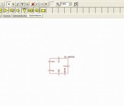
I've updated my Tina-TI to version 9.
The LM4780 model are included in this version, but as you can see in the image, there is no ground pin.
Where do I connect the ground on this LM4780 model ?
Do you have a working Tina schematic file of a LM4780 amp that you can post here ?
Thank
Bye
Gaetan
I've updated my Tina-TI to version 9.
The LM4780 model are included in this version, but as you can see in the image, there is no ground pin.
Where do I connect the ground on this LM4780 model ?
Do you have a working Tina schematic file of a LM4780 amp that you can post here ?
Thank
Bye
Gaetan
Attachments
Last edited:
Hello
I've updated my Tina-TI to version 9.
The LM4780 model are included in this version, but as you can see in the image, there is no ground pin.
Where do I connect the ground on this LM4780 model ?
Do you have a working Tina schematic file of a LM4780 amp that you can post here ?
Thank
Bye
Gaetan
What i understood is that GND pin is important only for specific working condition, principally for muting and undervoltage state, you can read about also in another tread here:
http://www.diyaudio.com/forums/chip-amps/105386-lm3886-pin7-gnd-current.html#post1258074
So you can simulate a normal working condition also without it.
How i already write, you can only make attention to connect the mute resistor to positive supply, instead of negative as in real circuit, becouse this is a bug of spice model.
I have not a clean schematic to post now, because i maked many esperiments to evaluate modding for simply, bridged, paralleled and bridged/paralleled configuration, again other solution on dual point of signal reaction for manupulate dampig factor, included some experiment to modification "My_ref" of Mauro Penasa, using other op-amp driver or discrete circuits and different mode to stabilize in frequency.
.
Startin by the datasheet schematic, is very easy Drawing a basic non inverting or inverting amplifier based on this chip, anyway, if you have some difficoulty, i can try to reedit and post a basic schematic but you can see the same on the datasheet on Texas site.
I have posted here only some message and I dont know if here I can share directly schematic .TSC file, i fear i must send it to you only by email
I hope my english could be comprehensible
")
Last edited:
Do not waste your time to simulate THD with these models. The nonlinearity is not modeled in these simple models. If it is modeled as good as the chips, anyone understand it can reverse engineer it with ease. The model needs every transistor and parasitic components to fully model the nonlinearity, more than full schematic, it is likely kept as secret. These models can only do small signal AC response, nothing else.
I have posted here only some message and I dont know if here I can share directly schematic .TSC file, i fear i must send it to you only by email
I hope my english could be comprehensible
Hello
To post it here you rename your schematic .TSC file into .txt
Thank
Bye
Gaetan
- Status
- This old topic is closed. If you want to reopen this topic, contact a moderator using the "Report Post" button.
- Home
- Amplifiers
- Chip Amps
- TI has new spice models for LM3886 LM3875 et all