cap C and resistor R7 do not need to be high rated.
The worst case voltage they could be exposed to during a mains fault incident would be around 4Vpk (when the paralleled diodes are passing 500A each). Vf is normally below ~0.8V when passing upto 25Apk.
A 50V cap and a 500mW resistor are man enough for the interference passing duty.
The mains receptacle should have it's PE connected to chassis at the incomer.
The Disconnecting Network can be connected to chassis at the point where it taps into the PSU/audio circuit. Do not take it to the PE connection.
Remove the two capacitors across the ON/OFF switch. The spark suppression cap (or better use an R+C suppressor) across the load after the switch.
Remove the two capacitors across the secondaries.
If you need some anti-ringing/snubbing components here, then use R+C snubber across the secondaries.
Last edited:
You have a direct link from PSU zero volts to case and a second link via the Disconnecting Network (DN) to the case.
You don't need two links.
You can make the DN optional by adding a switch in parallel to the R||C
You may find that closing, or opening the switch makes no difference.
You don't need two links.
You can make the DN optional by adding a switch in parallel to the R||C
You may find that closing, or opening the switch makes no difference.
Sorry Andrew. I misinterpreted your statement:
Just to clarify, I should tie the earth potential (equipment ground) to the chassis at the socket and tie the PCB ground terminal to the the chassis, i.e. shortest runs from each location?
Since there are 2 PCBs, should each ground terminal be tied to the mounting chassis or can one connect to the chassis and jumper to the other? or does it matter?
The mains receptacle should have it's PE connected to chassis at the incomer.
The Disconnecting Network can be connected to chassis at the point where it taps into the PSU/audio circuit. Do not take it to the PE connection.
Just to clarify, I should tie the earth potential (equipment ground) to the chassis at the socket and tie the PCB ground terminal to the the chassis, i.e. shortest runs from each location?
Since there are 2 PCBs, should each ground terminal be tied to the mounting chassis or can one connect to the chassis and jumper to the other? or does it matter?
It depends on how you are powering your amplifiers.......................Since there are 2 PCBs, should each ground terminal be tied to the mounting chassis or can one connect to the chassis and jumper to the other? or does it matter?
If the two PSUs are isolated from each other, then you NEED two separate connections to chassis.
If the two PSUs share their Zero Volts line, then you must use ONLY one connection to chassis.
I've never found insulators that size. I've used bulk thermopad, and I've used Kapton tape (with WHITE pc cpu thermal compound) and shoulder washers. I've also used black alloy radio transmitter heatsink (aluminum oxide) with chamfered holes filled with Arctic Ceramique, mainly because a small heatsink was cheap and worked fine. I've harvested mica manually with my pocketknife while bicycle touring. Once, I even used an old teflon skillet from the junk store (the teflon could be greased with Arctic Ceramique). Just mind the shoulder washers and chamfer/divot the hole so that tightening the bolt doesn't pull aluminum through your insulator (check with ohmmeter).Hi Daniel,do you know a place to order the multiwatt15 isolators for this board? Thanks
Thermal compound must be a white color. It could be Arctic Ceramic which is too thick so you have to squeegie/scrape it thin (its fantastic except for a wee spot of labor) or it could be GC 44 or it could be ordinary bulk white thermal grease; but don't use any of the metal colored stuff.
And, you have to use the shoulder washers as well as your ohmmeter to confirm that the tab doesn't electrically conduct to the heatsink. It is also important to secure the board so that it won't ever move to a different (possibly electrically conductive) spot on the heatsink. We wouldn't want that news to change during service. Bolt it down, then check again.
If you didn't set the gain too low for your choice of power voltage, then this amp ought to be easy and inexpensive to heatsink. Refer to Post#1 re gain/comp.
P.S.
It is not healthy to use this amp at full blast inside of a normal size dwelling; however, it could be used in a large open-floor-plan size house, likewise barn or pub. Do be mindful that a sure way to know when you have enough power is when you have too much.
My parallel TDA7293 with mods suggested by Daniel is currently driving my dipole woofers, and doing it very well I might add. Thanks Daniel")
Thanks! Glad to hear it. There was much attention paid to stability (efficiency while driving real speaker) and goodly, appropriate-proportion bass output.
Same thing will work for your midrange.
Some of you may be interested in this:
http://www.diyaudio.com/forums/grou...ell-powered-feedback-60-120w.html#post5354054
http://www.diyaudio.com/forums/grou...ell-powered-feedback-60-120w.html#post5354054
However, this works very well: Folsom EC7293: PVI Powered Frontend, 60/120w 8/4ohmSome of you may be interested in this:...
I still think I've nailed it for the bass and party amplifiers; but, if more elegance was needed, it looks like you have achieved it.
Also, Kudos on the abruptly better quality documentation!
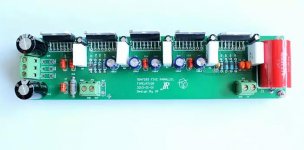
0.1R 5W 5% resistors connected to outstage of each chipWhat are these white prismatic components?
Best regards!
- Home
- Amplifiers
- Chip Amps
- TDA7293 Parallel kit from ebay (modular/slave style, no lossy emitter resistors)